| alt-azimuth mountings |
|
All equatorial mountings have a fundamental flaw - the polar axis must be aligned with the Earth's rotation axis. This means that unless the telescope is situated at the Earth's poles, the polar axis will be inclined relative to the ground (or, strictly speaking, the local gravity vector), thereby creating stresses on the axes which vary as the telescope moves. The sheer size of the structure required to support the 3.9m Anglo-Australian Telescope, shown in figure 33, demonstrates the impractability and expense of mounting telescopes significantly larger than this on an equatorial mount; the largest equatorially-mounted telescope ever built - the 5m Hale Telescope - is only slightly larger than this.
One solution would be to reduce the length of the horseshoe so that it is stiffer, but this then reduces the space available beneath the primary mirror to mount instrumentation. A much better solution is to use a fork mount, but incline the tines so that they are parallel with the local gravity vector. This places the centre of mass of the telescope directly above the point where the telescope is mounted on the ground, which, for a given mass of mount, gives a much stiffer structure that is largely free from variable stresses. In this design, the length of the tines can also be increased to provide plenty of room for instrumentation without significantly degrading the structural stability.
| figure 34: |
Schematic of an alt-azimuth mounting.
|
A mounting of this type is called an alt-az or alt-azimuth mount, as its two axes are aligned with respect to the altitude and azimuth axes of the horizontal coordinate system, as shown in figure 34. The tines of the fork are mounted on a rotating pad which acts as the azimuth axis. The altitude axis is formed by mounting both sides of the telescope near the top of the tines. Two examples of alt-azimuth mounts are shown in figure 35.
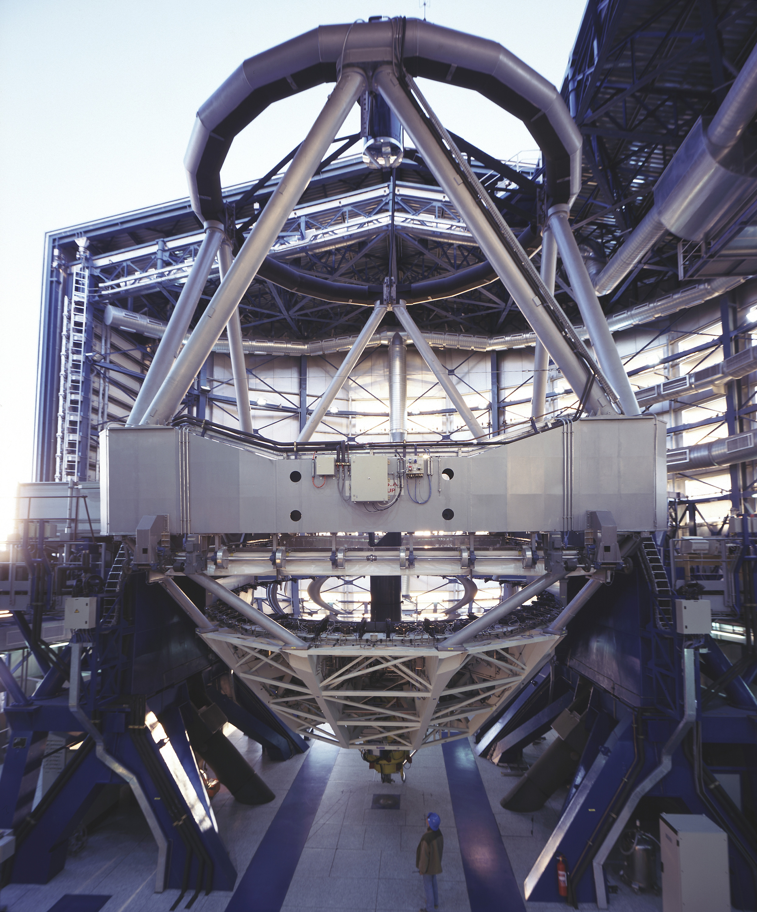
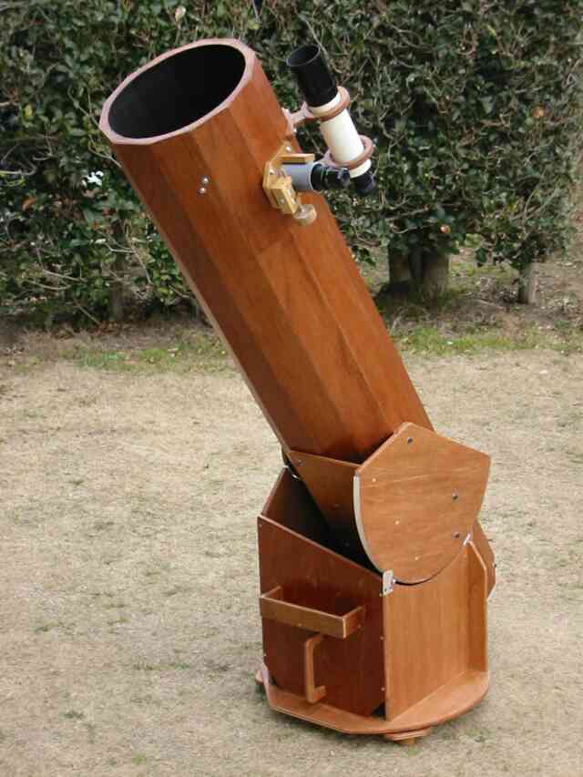
| figure 35: |
Two examples of alt-azimuth mountings. Left: A photograph of the 8.2m Very Large Telescope
in Chile, which is a Ritchey-Chretien design. Right: A
photograph of an 8-inch amateur telescope - a Newtonian on a Dobsonian
mount. The Dobsonian was popularised by the amateur astronomer John Dobson
and is a particularly cheap and stable alt-azimuth design.
|
The primary disadvantage of the alt-azimuth design is that it is necessary to move both axes simultaneously in order to track the motion of an object as it moves across the sky due to the rotation of the Earth. Not only this, but the speed that the axes have to be moved varies depending on where the object is in the sky. The calculations required to move the two axes are quite complex (a coordinate conversion between the equatorial and horizontal systems) and need to be performed many times a second. This requires the use of a computer, but computers only became readily available in the 1970's. It is for this reason that every major research telescope made since the 1980's uses an alt-azimuth mount, but every telescope made before this time was mounted equatorially.
Even with computer control, the azimuth axis has a finite speed limit which means it is unable to track objects which pass within a few degrees of the zenith. This is referred to as the zenith blind spot, and is more of an annoyance rather than a major problem, as it means that observations have to be halted for a few minutes whilst the telescope catches up with the object on the other side of the zenith. Another problem with alt-azimuth mounts is that the field of view rotates as an object is tracked across the sky, which if uncorrected would lead to the trailing of star-light in an image. To compensate for this, research telescopes are usually fitted with rotating mounts to which the instruments are attached, as shown in figure 38. These rotators rotate the instruments in the same direction and at the same rate as the field of view rotates. A similar effect can also be achieved by keeping the instrument fixed, but using derotation optics in front of the instrument.