Some astronomical instruments, e.g. high-resolution spectrographs, are
too large, too heavy and too sensitive to flexure to be mounted below
the primary mirror of a Cassegrain or Ritchey-Chretien
telescope. It is possible, however, to provide a stable platform for
an instrument by redirecting the light off the telescope using one or
more additional mirrors, as shown in figure
36.
|
figure 36:
|
Schematic of a Cassegrain telescope showing the use of a tertiary
mirror to direct light to a coudé or Nasmyth focus. The same
diagram applies to a Ritchey-Chretien telescope, except that the
primary would be hyperbolic rather than parabolic. In the case of
the coudé focus, additional flat mirrors after the tertiary are
sometimes employed to direct the light to a given location off the telescope.
|

The coudé focus (from the French word for elbow) is
usually found on equatorially-mounted telescopes. A typical
coudé design uses a flat mirror (the tertiary) to
redirect the light along the declination axis of the telescope and
then another flat mirror (the quaternary) to direct the light
down the (fixed) polar axis into a room near the base of the telescope
in which the instrument is mounted, as shown in figure 37. The instrument hence remains
stationary whilst the telescope moves. In addition to the light lost
at each reflection, the main drawback of the coudé design is
that the field of view rotates as the telescope tracks an object, so
derotation optics are usually required to correct for this (which
causes yet more light loss).
|
figure 37:
|
Left: A
photograph of the ESO 3.6m Cassegrain reflector in Chile. A schematic of the four mirrors
and light path of a typical coudé arrangement are overlaid.
Right: A
photograph of a typical coudé room. The light from
the telescope comes through the pipe at the upper-left and falls
on the instrumentation on the optical bench.
|


The Nasmyth focus (named after the 19th-century Scottish
engineer James Nasmyth) is usually found on alt-azimuth mounted
telescopes. A tertiary mirror redirects the light horizontally along
the altitude axis to the side of the telescope. Hence the Nasmyth
focus moves with the telescope azimuth axis, but the beam remains
horizontal with respect to the ground. Like in the coudé
design, the field of view rotates at the Nasmyth focus whilst tracking
an object, but this can be compensated for by using derotation optics
or by mounting the instrument on a rotating platform which rotates
with the field of view, as shown in figure 38.
|
figure 38:
|
A photograph of an instrument (ULTRACAM) mounted on one of the
Nasmyth focii of the 8.2m Very Large Telescope in Chile.
|

Many modern research telescopes have two Nasmyth foci, one at each end of
the altitude axis. The tertiary mirror can then be tilted to direct
light to either Nasmyth focus, or retracted to allow light to pass
straight through to the Cassegrain (or Ritchey-Chretien) focus. This
configuration allows three different instruments to be permanently
attached to the telescope, each accessible at the flick of a switch,
giving astronomers significantly more flexibility. Some telescopes
have horizontal platforms at the tops of the tines, such as the one
the person is standing on in figure 38. It is
possible to mount particularly large, heavy or sensitive instruments
horizontally on these Nasmyth platforms using an optical bench and
derotation optics. These instruments are often enclosed in
light-tight, temperature-controlled laboratories, such as shown in figure 39.
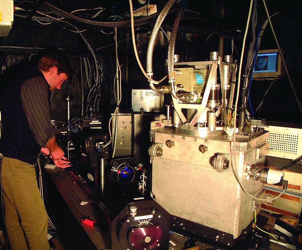
|
figure 39:
|
Left: A photograph
of the 4.2m William Herschel Telescope on La Palma showing the two
laboratories (GHRIL and GRACE) mounted at the two Nasmyth focii. It should be noted that
both labs rotate with the azimuth axis of the telescope. The black turret
at the centre of the image houses the tertiary mirror. Right: A
photograph of the
inside of one of the laboratories. Light from the telescope enters the lab
just behind where the person is standing, passing through some derotation
optics before entering the complex instrumentation (an adaptive
optics imager) on the optical bench.
|


©Vik Dhillon, 3rd September 2010