| equatorial mountings |
|
A telescope mounting must allow the telescope to be pointed at any point in the sky and track the object as it moves due to the rotation of the Earth, maintaining the relative alignment of the optics as it does so.
Before the 1980's, all large telescopes were mounted on equatorial mountings. This system is illustrated in figure 29. One axis is parallel to the Earth's rotation axis and is known as the polar axis. The second axis is at right angles to this and is known as the declination axis. The beauty of this design is that there is a direct relation between the equatorial coordinates of an object and the axes of the telescope: rotation about the polar axis scans out a circle of constant declination and varying right ascension; rotation about the declination axis scans out a circle of constant right ascension and varying declination. As well as making it easy to point to an object, this also makes it simple to track the motion of an object due to the Earth's rotation by driving just the polar axis at an equal angular velocity, but in the opposite direction, to the angular velocity of the Earth on its rotation axis.
| figure 29: |
Schematic of an equatorial mounting.
|
In practice, unfortunately, it isn't possible to keep an object perfectly in the centre of the field of view merely by rotating the polar axis at the sidereal rate. This is due to a number of factors, including inaccuracies in the telescope drive systems, flexure, and misalignment of the mount axes with respect to the celestial pole. To combat this image motion, which would cause smearing in long exposures, it is necessary to guide, where small adjustments to the position of the telescope are made to keep the object at the desired position in the focal plane. On all professional telescopes, this is done automatically using an autoguider, which continuously measures the position of a guide star somewhere in the field of view and nudges the telescope to keep the guide star locked onto a particular pixel on the autoguider's detector.
There are several different types of equatorial mounting; which one is adopted for a particular application depends on the size and type of the telescope being mounted. We shall look at the three main equatorial mount designs here: the German mounting, the fork mounting and the English mounting.
The German mounting
An example of a German equatorial mounting is shown in figure 30. In this design, the declination axis is in the form of a beam across the top of the polar axis. The telescope is attached to one end of the beam and a counterweight to the other. In large German mounts, the polar axis is often supported on a pier. The advantage of the German design is that it can handle both refractors and reflectors of all focal lengths, and it can access all areas of the sky. The disadvantage is that it suffers from the need for meridian reversal: to prevent the telescope from crashing into the pier whilst tracking objects crossing the observer's meridian, it is usually necessary to stop the observations, rotate the polar and declination axes through 180o (so placing the telescope on the opposite side of the pier), and then restart the observations. This, and the large footprint of the German mount due to its long declination axis, can make it rather cumbersome to use, a problem exacerbated by the sometimes awkward positioning of the focal plane of the telescope.
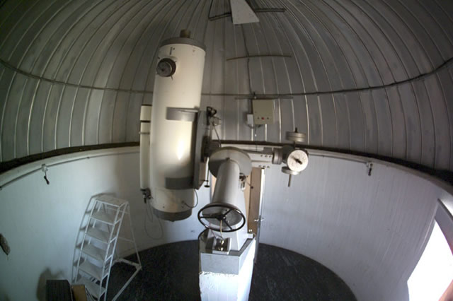
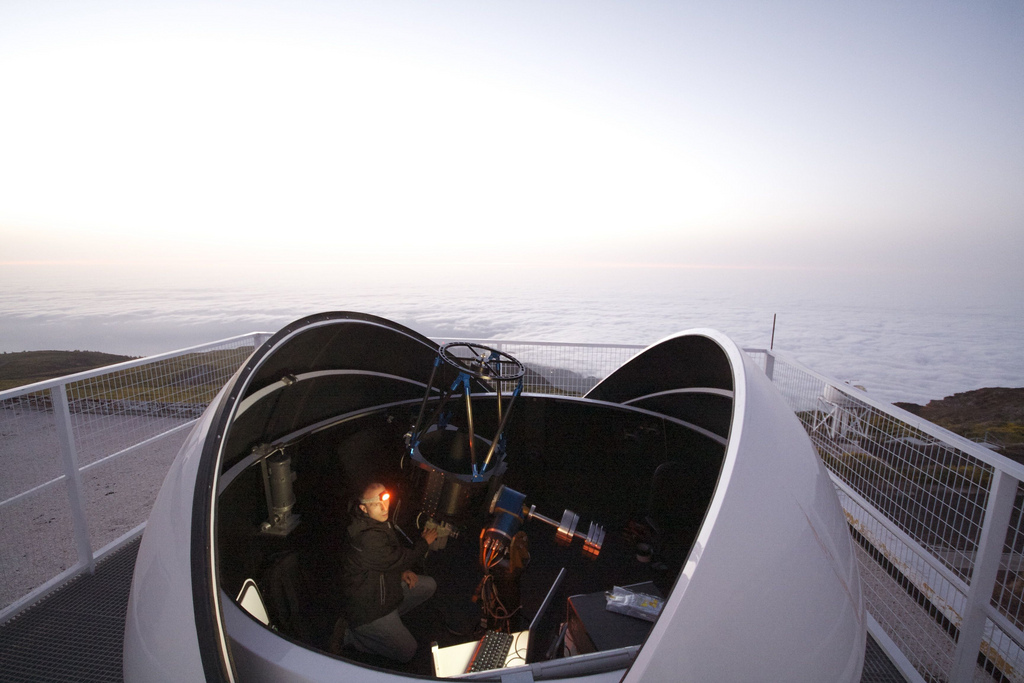
| figure 30: |
Examples of German equatorial mountings. Top left: A photograph of a 120mm refracting telescope.
Top right: A photograph of the 50 cm Mons reflector on Tenerife.
Bottom: pt5m, the Durham-Sheffield 0.5m robotic telescope on La Palma.
|
The German mount is a popular choice in the amateur astronomy market, but is rarely used in larger research telescopes. The reason for this is that the offset mounting of the telescope induces large torques which cause bending of the telescope and axes, and stresses on the bearings.
The fork mounting
The equatorial fork is probably the most popular mount found in the amateur astronomy market today, and is also the mount of choice for many large equatorially-mounted research telescopes. The design of the polar axis in a fork mount is very similar to that of the German mount. However, rather than supporting just one side of the declination axis passing through the telescope, as in the German mount, the fork mount supports the declination axis on both sides of the telescope, as shown in figure 31.
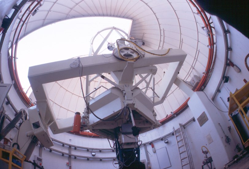
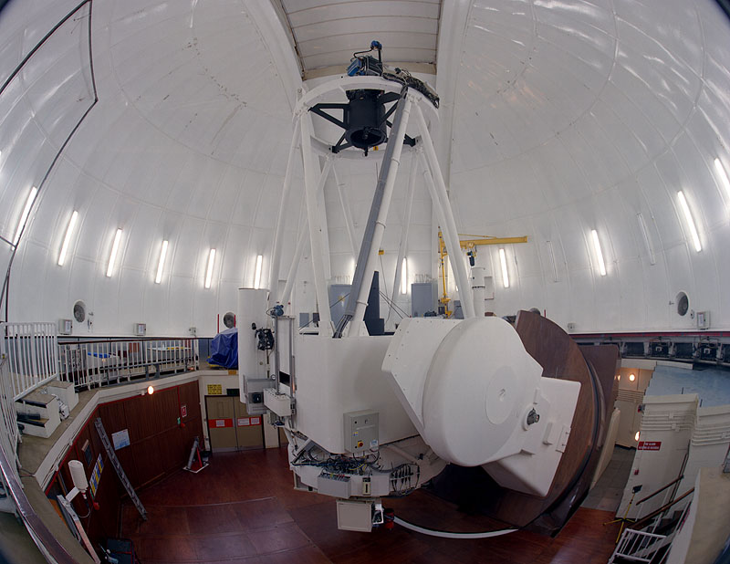
| figure 31: |
Examples of equatorial fork mountings. Left: A
photograph of an 8-inch Schmidt-Cassegrain telescope. Right:
A photograph
of the reflecting 2.5m Isaac Newton Telescope on La Palma.
|
The fork mount has a number of advantages over the German mount. First, it does not require meridian reversals. Second, it is generally easier to access the focal plane. Third, no large counterweights are required and hence fork mounts are usually more compact than German mounts. There are disadvantages to the fork mount, however. The main one is that the fork arms (or tines) tend to be short in length to retain stiffness. This then makes it difficult to mount refractors, which generally have longer tubes than reflectors, without losing access to the sky around the celestial pole. Even if the telescope tube is short enough to rotate freely between the tines, the design still restricts the space for instrumentation mounted beneath the primary mirror.
For large telescopes, the fork mount tends to be stiffer than the German mount, thanks to the way in which both sides of the declination axis passing through the telescope are held. In both the German and fork designs, however, the telescope is mounted at the end of the polar axis, which stresses the bearings and induces flexure.
The English mounting
The English mounting, or yoke mounting, aims to reduce the flexure in the polar axis inherent in the German and fork mounts by supporting both sides of the polar axis of the telescope on two piers, as shown in figure 32. A cradle, or yoke, is used as the polar axis, and both sides of the declination axis of the telescope are supported by it.
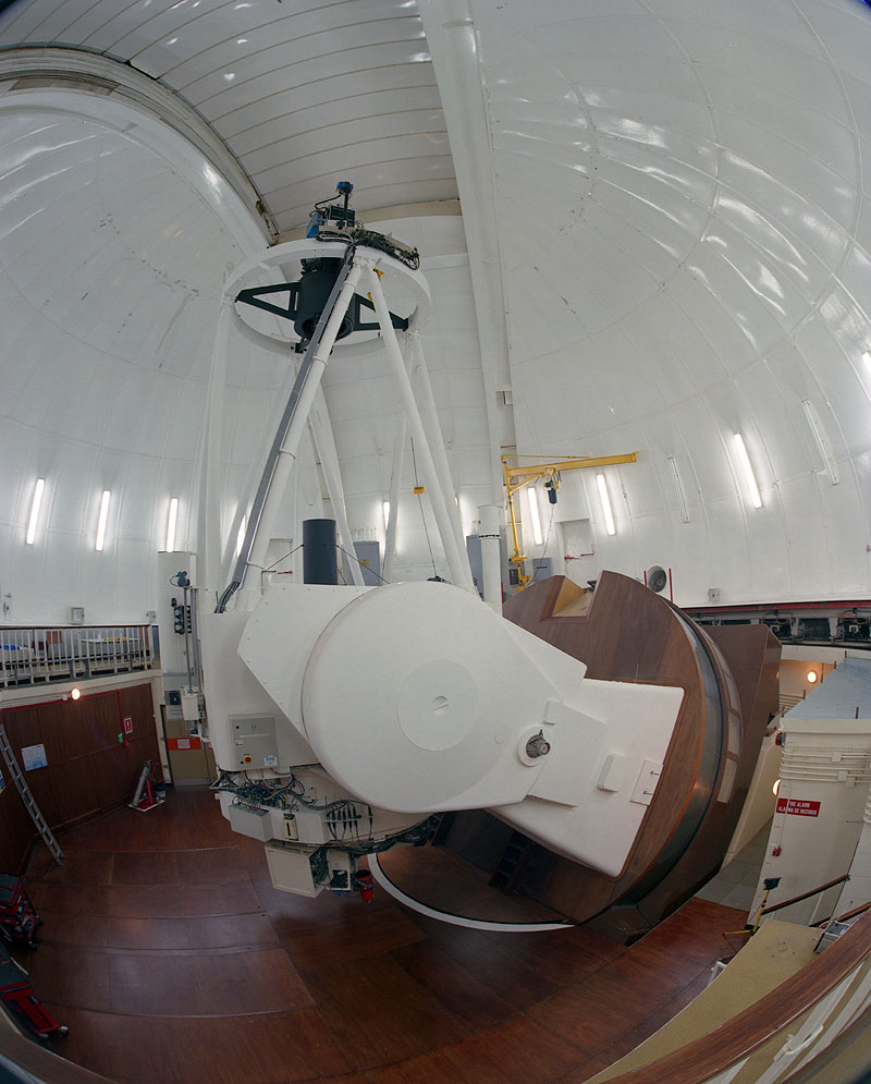
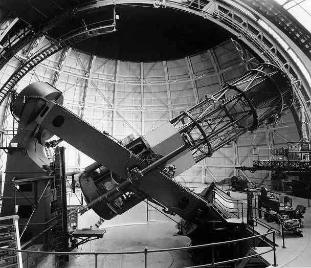
| figure 32: |
Two examples of English mountings. Left: A
photograph
of the 1.5m Carlos Sanchez Telescope on Tenerife. Right: A
photograph of the 100-inch Hooker Telescope in California, with which Edwin Hubble
discovered the expansion of the Universe.
|
Although providing stable polar and declination axes, the disadvantage of the English mounting is that the sky around the celestial pole is unobservable, irrespective of the length of the telescope. One way round this is to use a modified English mounting, shown in the left-hand panel of figure 33, where the yoke is replaced by a single beam. The declination axis is mounted in a similar way to the German mount, with the telescope at one end and a counterweight at the other. Hence, although the modified English design provides access to the sky around the celestial pole for telescopes of all lengths, it does so at the expense of reintroducing the flexure in the declination axis inherent to the German design.
| figure 33: |
Left: A photograph of the 1.9m Radcliffe Telescope in South Africa, which
has a modified English mounting. Right: A
photograph of the 3.9m Anglo-Australian Telescope in New South
Wales, which has a horseshoe mounting.
|
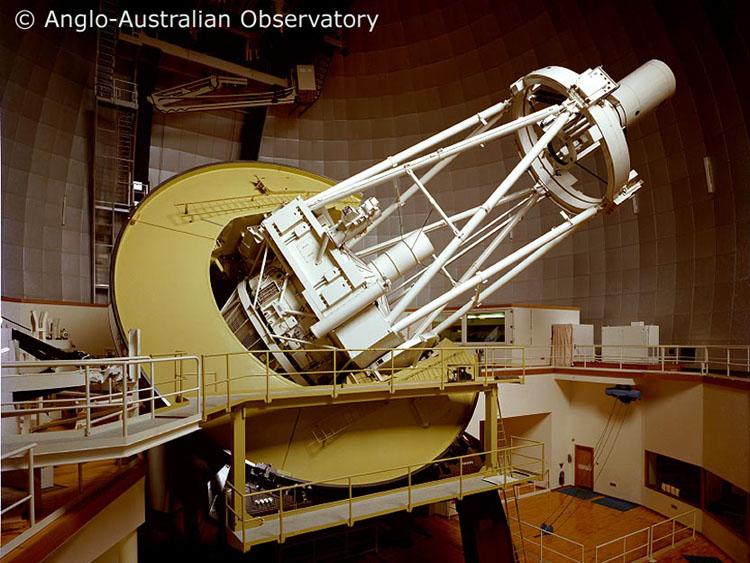
Another variant of the English mounting is shown in the right-hand panel of figure 33. This is known as the horseshoe mounting, or the open yoke mounting. It aims to combine the advantages of the German, English and fork mounts, whilst eliminating their disadvantages. It does this by adopting an English mount design with the end of the yoke open, thereby adopting a horseshoe shape, so that the telescope can still point towards the celestial pole. The mount is relatively compact, no meridian reversals are required, the polar regions are accessible, and all masses lie between their points of support. It is no suprise, therefore, that the world's largest telescopes built before the 1980's were all horseshoe mounted, including the Mayall 3.8m Telescope on Kitt Peak, the 5m Hale Telescope, and the 3.9m Anglo-Australian Telescope. Note the subtle difference in the location of the declination axis in the latter two telescopes; in the Anglo-Australian Telescope it is located within the horseshoe itself, whereas in the Hale Telescope it is within a yoke.