| autoguiding |
|
We have already seen that equatorial telescopes can track the motion of an astronomical target across the sky by rotating the polar axis at the sidereal rate. In practice, it isn't possible to keep an astronomical object perfectly in the centre of the field of view by doing this. This is due to a number of factors, including imperfections in the telescope drive systems, flexure, and misalignment of the mount axes with respect to the celestial pole. The same problem also affects alt-az telescopes, of course, but in this case the misalignment is with respect to the horizon and zenith.
To combat this image motion, which would cause smearing in long exposures, it is necessary to guide, where small adjustments to the position of the telescope are made to keep the object at the desired position in the focal plane. Although this can be done manually using the telescope handset, it is usually done automatically using an autoguider, which continuously (typically on 0.1-1 s timescales) measures the position of a guide star somewhere in the field of view and nudges the telescope to keep the guide star locked onto a particular pixel on the autoguider's detector (see figure 55). To prevent over correction, i.e. "chasing" the guide star in response to fluctuations in its position due to seeing, and also to allow for the fact that the guide star will most probably have moved slightly in the time it takes to make the position measurement and correct for it, it is best to move the telescope by only a fraction of the measured offset. This parameter, called the aggressiveness or gain of the autoguider correction, typically has a value of ~0.3.
| figure 55: |
The principle of autoguiding. Autoguiding begins at time
t1. At time t2, the star
has drifted by Δx, Δy pixels on the
autoguider CCD. With a knowledge of the plate scale and orientation of
the field of view, these pixel shifts are converted to arcseconds of motion
of the two telescope axes. The shifts are multiplied by the aggressiveness
(a factor between 0 and 1), and then applied to the telescope
in order to shift the star back towards its initial position.
|

There are two main types of autoguider - off-axis autoguiders and autoguiders on separate guidescopes - each of which are described below.
off-axis autoguiders
Off-axis autoguiders use stars located in the periphery of the field of view, outside the area of scientific interest. On small telescopes, it is common to incorporate an off-axis autoguider CCD alongside the main science CCD, and house both in the same camera body. An example of such an arrangement is shown in figure 56. The advantage of this setup is that there are no moving parts and there is no flexure between the autoguider CCD and the science CCD, which means that any corrections measured from a star in the autoguider CCD will be applicable to the science target in the main CCD. The disadvantage of off-axis autoguiders of this type is the lack of flexibility in choosing a guide star - if no suitable star falls on the small autoguider CCD, then the whole camera body has to be rotated and/or the telescope has to be moved until one is found. Such autoguiders also have to peer through the same filter that is being used for the scientific observations, significantly reducing the amount of light from the guide star in the short exposure times and hence reducing the guiding accuracy.
| figure 56: |
Left: Photograph of the
657 x 495 pixel TC-237 off-axis autoguiding CCD sitting above the main
KAF-1602E science CCD in an SBIG ST-8 camera. Right: Outline of the
field of view of an SBIG ST-7 camera on an 8"
Schmidt-Cassegrain telescope, showing the galaxy M51 on the science
CCD and a bright guide star on the integral off-axis autoguiding CCD. |


Large, professional telescopes tend to use a different form of off-axis autoguider, where a separate autoguider CCD is mounted on an adjustable stage which is able to select any guide star in an annulus around the central field of view (see figure 57). The great advantage of this setup is that it is almost always possible to find a suitable guide star by moving the autoguider CCD, and this process is often automated. Another advantage is that the autoguider CCD is a completely separate system, and hence can be used to autoguide any instrument which accesses the centre of the field of view. The disadvantage of this autoguider design is the complexity and cost of the system, and the fact that the autoguider CCD may experience different flexure to the science CCD, resulting in inappropriate guiding corrections being applied.
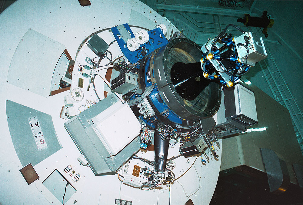
| figure 57: |
Off-axis autoguiding using pick-off optics. Left: photograph
of the Cassegrain focus of the 4.2 m William Herschel Telescope on La
Palma. Autoguiding is provided by the blue-coloured Acquisition &
Guidance (A&G) unit, which uses an internal pick-off mirror that can
travel radially and azimuthally in an annulus around the centre of the field of
view. Right: photograph
of a Hutech Mitsuboshi off-axis guider for the amateur market. The
pick-off prism directs off-axis light upwards for autoguiding. The
prism can be manually adjusted radially and azimuthally to select different
guide stars.
|


guidescopes
A guide scope is a separate, smaller-aperture telescope equipped with a CCD autoguider, which is mounted on the side of the main telescope, as shown in figure 58. The advantage of this setup, which is usually only found on amateur telescopes, is that the guide scope generally has a short focal length and hence wide field of view, resulting in a high probability of finding a bright guide star somewhere on the autoguider CCD. No moving parts are required and, assuming it is a bright point source, even the science target itself can be selected as the guide star. The disadvantage of a guide scope is that it can experience significantly different flexure to the main telescope as it tracks an object across the sky, resulting in a gradual drift of the field on the science CCD. Another disadvantage is that the short focal length of the guide scope provides a large plate scale, which means that small movements in the position of the guide star may be difficult to detect.
| figure 58: |
A photograph of ROSA,
the 10" robotic telescope on the roof of the Department of Physics and
Astronomy at Sheffield, with the dome removed. The
piggy-back mounted guide scope, a 3-inch refractor, can be seen on top
of the main telescope. A CCD autoguider has been inserted in place of
the eyepiece.
|
