ULTRASPEC will be tested for the first time on-sky on 1-4 December 2006 on the EFOSC2 spectrograph mounted at the Cassegrain focus of the ESO 3.6-m telescope at La Silla. This document presents a plan for this commissioning run.
The hardware and software used for ULTRASPEC are virtually identical to those developed and used for ULTRACAM, which has seen 23 successful nights of operation on the VLT.
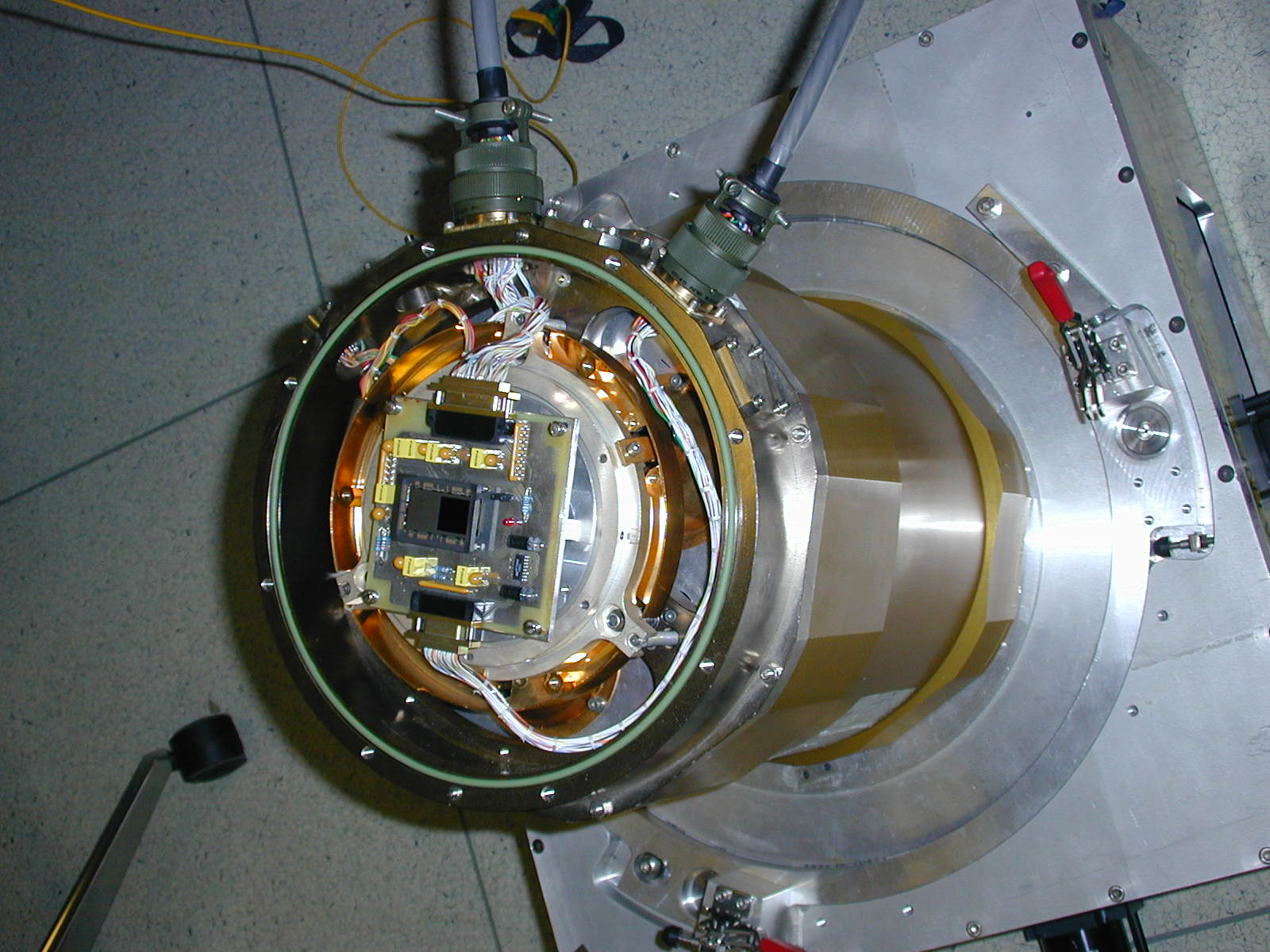
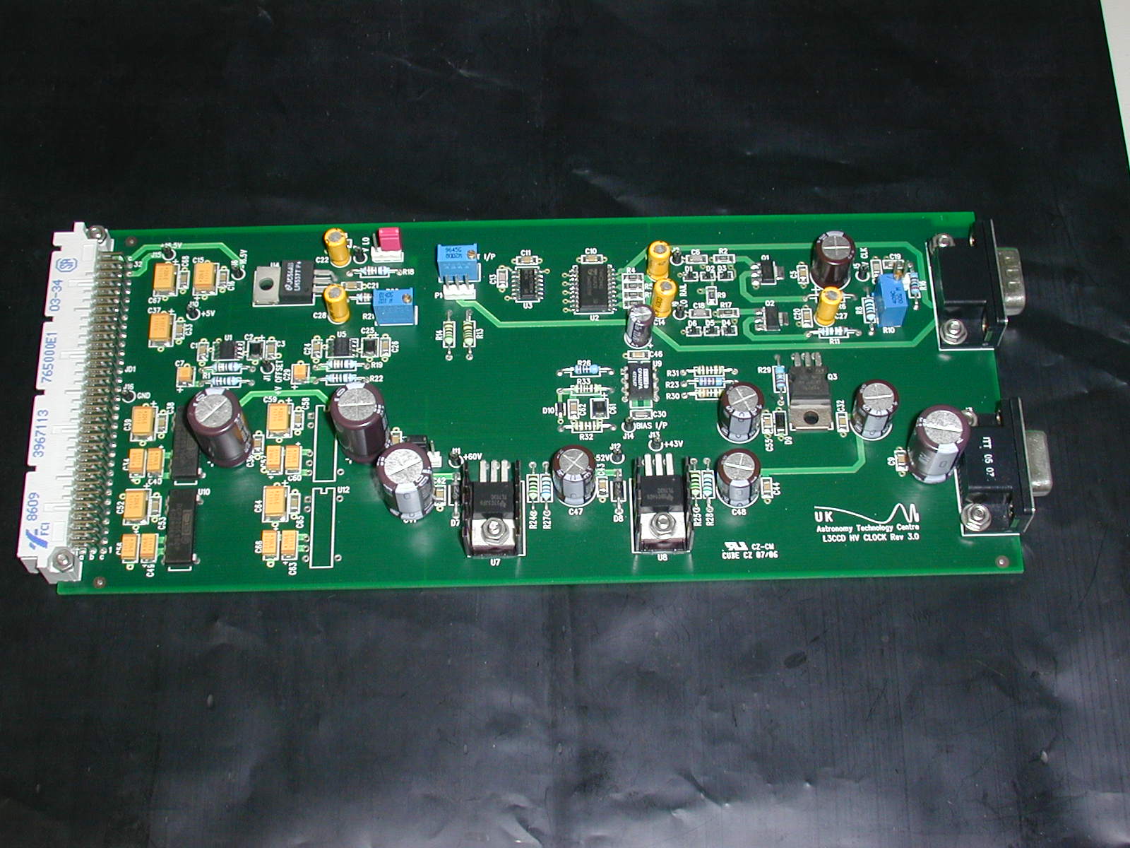
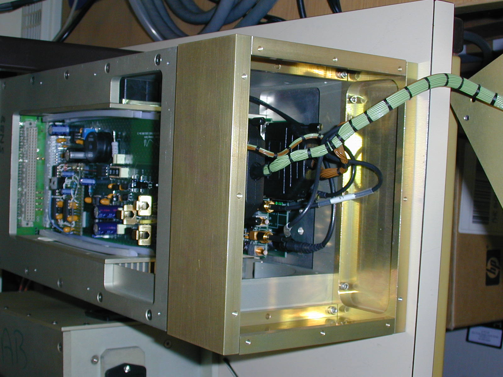
At the heart of ULTRASPEC is an E2V CCD201-20, which is a low-light-level CCD (L3CCD). This chip is mounted in a standard (old-style) ESO cryostat, cooled by liquid nitrogen and regulated by a Lakeshore temperature controller. The chip is controlled by a San Diego State University (SDSU) Generation III CCD controller, which incorporates a custom-made, high-voltage clock board to power the serial gain register. The SDSU controller is hosted by a rack-mounted dual-processor PC running Linux patched with RealTime Application Interface (RTAI) extensions. The use of RTAI allows one processor to be strictly controlled so as to obtain accurate timestamps from the Global Positioning System (GPS) antenna located outside the dome and connected to the PC via a serial port. The images below show, from left-to-right, the L3CCD chip in the ESO cryostat, the new high-voltage clock board, and the SDSU CCD controller.
|
|
The instrument control PC communicates with the SDSU controller via a Peripheral Component Interconnect (PCI) card and two 250 MHz optical fibres. As well as communicating through the fibres, the SDSU controller also has the ability to interrupt the PC using its parallel port interrupt line, which is required to perform accurate timestamping. Data from the CCD is passed from the SDSU PCI card to the PC memory by Direct Memory Access (DMA), from where the data is written to a high-capacity SCSI disk array. All of the real work in reading out the CCD is performed by the SDSU controller; the PCI card merely forwards commands and data between the instrument control PC and the SDSU controller.
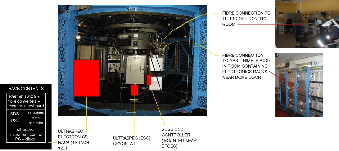
All of the hardware components mentioned above will be located in the Cassegrain cage of the telescope, as shown in the image below. All connections between the hardware components of ULTRASPEC will occur within the Cassegrain cage, apart from two fibres, one of which must connect with the ULTRASPEC GPS system and the other which must connect to the telescope control room.
|
The SDSU controller and PCI card both have on-board digital signal processors (DSPs) which can be programmed by downloading assembler code from the instrument control PC. A user wishing to take a sequence of windowed images with ULTRASPEC, for example, would load the relevant DSP application onto the SDSU controller (to control the CCD) and PCI card (to handle the data). The user can also modify certain parameters, such as the exposure time or binning factors, by writing the new values directly to the DSP's memory.
The SDSU controller and PCI card both have on-board digital signal processors (DSPs) which can be programmed by downloading assembler code from the instrument control PC. A user wishing to take a sequence of windowed images with ULTRASPEC, for example, would load the relevant DSP application onto the SDSU controller (to control the CCD) and PCI card (to handle the data). The user can also modify certain parameters, such as the exposure time or gain factor by writing the new values directly to the DSP's memory.
Stamping CCD frames with start times accurate to a small fraction of the typical exposure time is a key requirement for any astronomical instrument. In ULTRASPEC, with frame rates of up to 100 Hz, this requirement is particularly severe, as it demands timestamping accurate to better than a millisecond. Without this level of accuracy, for example, it would be impossible to compare data taken simultaneously with ULTRASPEC and an X-ray satellite or radio telescope.
Whenever an exposure is started, the SDSU controller sends an interrupt to the instrument control PC which, thanks to the use of RTAI, immediately writes the current time (see below for how this is determined) to a First-In First-Out (FIFO) buffer. The data handling software then reads the timestamp from the FIFO and writes it to the header of the next buffer of raw data written to the PC memory. In this way, the timestamps and raw data always remain synchronised.
The clock provided on most PC motherboards is not able to provide the current time with sufficient accuracy for our purposes, as it typically drifts by many milliseconds per second. The solution adopted by ULTRASPEC is to use a PCI-CTR05 9513-based counter/timer board, manufactured by Measurement Computing Corporation, in conjunction with a Trimble Acutime 2000 smart GPS antenna. Every 10 seconds, the GPS antenna reports UTC to an accuracy of 50 nanoseconds. At the same time, the number of ticks reported by the counter board is recorded. At a later instant, when a timestamp is requested, the system records the new value of the counter board, calculates the number of ticks that have passed since the last GPS update, multiplies this by the duration of a tick (which we have accurately measured in the laboratory) and adds the resulting interval to the previous UTC value reported by the GPS. Since the counter board ticks at 1 MHz, to an accuracy of 100ppm, this is a much more reliable method of timestamping than using the system clock of the PC.
Laboratory measurements indicate that the timestamping in ULTRACAM has a relative (i.e. frame-to-frame) accuracy of approximately 50 microseconds. The absolute timing accuracy of ULTRACAM has been verified to an accuracy of order 1 millisecond by comparing observations of the Crab pulsar with the Jodrell Bank Monthly Ephemeris. Since ULTRASPEC uses an identical timestamping system to ULTRACAM, we expect ULTRASPEC to be similarly accurate.
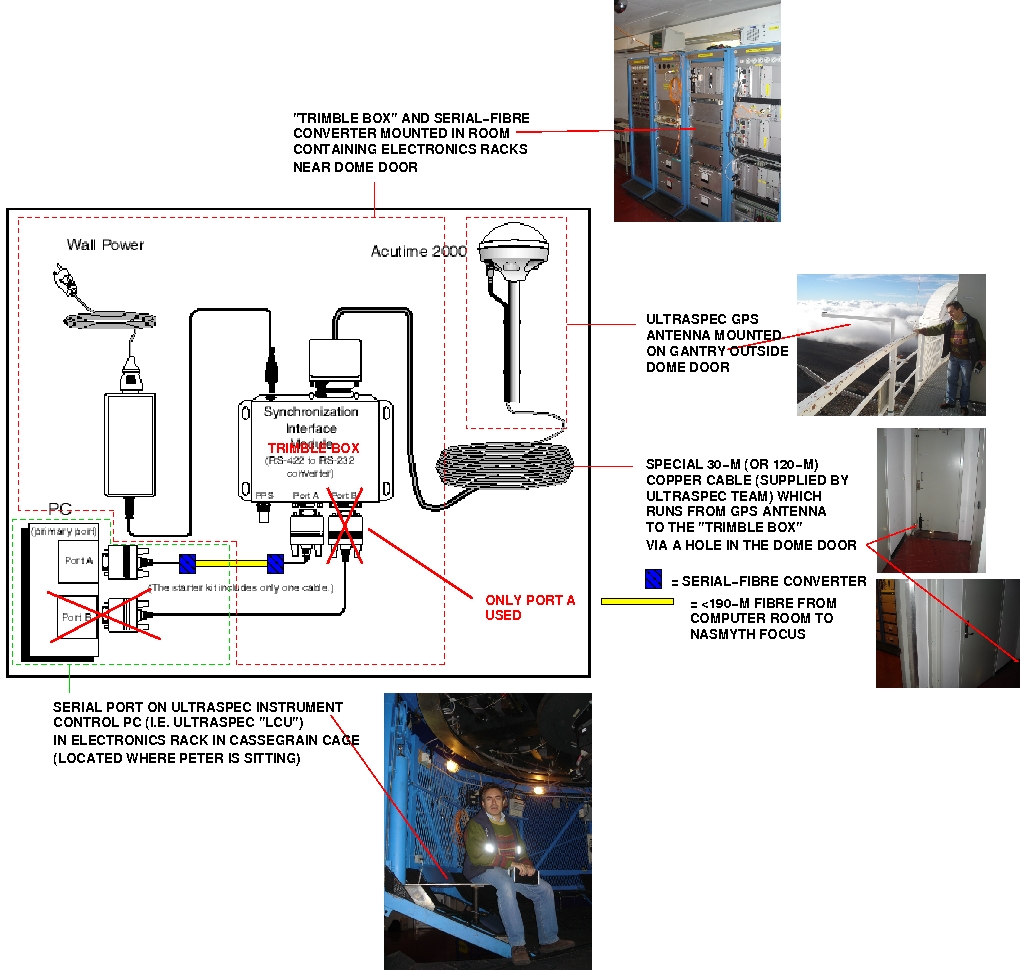
The GPS antenna must be located so that it can see an appreciable fraction of the sky, as the more GPS satellites is can detect, the more accurate its timing. We propose the solution depicted in the image below, where the ULTRASPEC GPS antenna is located on the gantry outside the dome door, the signal is converted from copper to fibre in the electronics-rack room near the dome door, and the signal then routed by fibre to the Cassegrain cage (where it is converted back to copper again for input to the ULTRASPEC instrument control PC). Note that this is an identical GPS setup to the one that has been successfully used for ULTRACAM at the VLT.
|
ULTRASPEC can generate up to 1 MByte of data per second. In the course of a typical night, therefore, it is possible to accumulate up to 50 GBytes of data, and up to 200 GB GBytes of data in the course of the four nights we have on EFOSC2. To handle these high data rates, ULTRASPEC has a dedicated pipeline data reduction system, written in C++, which runs on a linux PC or Mac located in the telescope control room and connected to the instrument control PC via a dedicated 100BaseT LAN.
Data from a run on an object with ULTRASPEC is stored in two files, one an XML file containing a description of the data format, and the other a single, large unformatted binary file containing all the raw data and timestamps. This latter file may contain thousands of individual data frames, each with its own timestamp. The data reduction pipeline grabs these frames from the SCSI disk array by sending HTTP requests to a file server running on the instrument control PC.
The ULTRASPEC data reduction pipeline has been designed to serve two apparently conflicting purposes. Whilst observing, it acts as a quick-look data reduction facility, with the ability to display spectra and trailed spectra in real time, even when running at the highest data rates of up to 1 MByte per second and at the highest frame rates of up to 0.1 kHz. After observing, the pipeline acts as a fully-featured spectroscopic reduction package, including optimal extraction. To enable quick-look reduction whilst observing, the pipeline keeps many of its parameters hidden to the user and allows the few remaining parameters to be quickly skipped over to generate spectra and trailed spectra in as short a time as possible. Conversely, when carefully reducing the data after a run, every single parameter can be tweaked in order to maximise the signal-to-noise of the final data.
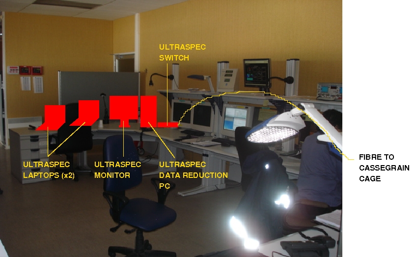
The ULTRASPEC data reduction pipeline, and the ULTRASPEC GUI (which controls the instrument), will run on desktop/laptop PCs located in the telescope control room, as shown in the photograph below. The only link required to the instrument will be a fibre running between the control room and the Cassegrain cage.
|
The ULTRASPEC consortium, consisting of astronomers and engineers from the Universities of Sheffield, Warwick and the UK Astronomy Technology Centre, will be responsible for the freight, installation/de-installation and operation of the instrument at La Silla. We will, however, require ESO technical support with:
ULTRASPEC's system architecture follows the ESO model, where the instrument has a Local Control Unit (LCU; a rack-mounted, dual-processor linux PC located in a rack near the cryostat at Cassegrain) which can be controlled over a LAN by any workstation that is able to open an xwindows session on it. In other words, no dedicated instrument control hardware (other than a standard desktop PC) is located in the control room. Also, since all communications between the instrument at Cassegrain and the control room will be via the LAN, no dedicated cabling between the instrument at Cassegrain and the control room is required. There is no need for physical proximity or local intervention to ULTRASPEC during observations - all status and controls as well as reset/stand-by/restart procedures are under software control and hence accessible via the LAN.
To ensure that our high data rates do not adversely affect other users of the La Silla LAN, and to ensure that these other users do not adversely affect the operation of ULTRASPEC, we propose a similar solution to the one adopted for ULTRACAM on the VLT - a dedicated fibre routed from the Cassegrain cage to the control room with our own ethernet switches at each end to create a private LAN. We also request an internet connection to the outside world.
Finally, it should be noted that ULTRASPEC is a completely stand-alone instrument, so no connection to the Telescope Control System is required. All data will be archived on hard disks provided by the ULTRASPEC team. If requested, a copy of these data will be passed to ESO for public archiving at the end of the run.
Alain Gilliotte (ESO) has informed us that the L3CCD must be aligned so that it is parallel to within 0.2 degrees with the cryostat flange (which corresponds to a difference of 0.05mm in focus position from one side of the chip to the other), and within 0.5mm of its nominal focus distance from the cryostat flange. We have determined that the latter figure is 14mm (measured from the technical drawings ESO gave us along with the cryostat). This alignment will be performed in the lab at Edinburgh using a travelling microscope mounted on the cryostat flange. The CCD tilt is the most critical factor for image quality, as the depth of focus of the EFOSC2 camera is very small; a poor focus can be compensated to some extent by the collimator, and poor centering would only result in additional vignetting.
Once at the telescope, the ULTRASPEC (ESO) cryostat will have to be aligned with respect to EFOSC2, using the following procedure:
Note that the above procedure requires night-time access to EFOSC2, and hence can only be done on the setup night (Dec 1). Emilio Barrios (ESO) estimates that it should take approximately 2 hours to complete. Any time remaining on this night will be spent performing the observations described below.
Below is a list of the items that are to be shipped to La Silla from the UK. Items marked with a * mean that some work remains to be done to procure, make or check the item.
A detailed plan describing how the ULTRASPEC team will use the 3 nights allocated to the project will appear here shortly.