These instructions tell you how to mount ULTRACAM on the WHT. They were written following an installation on 10th July 2013 by Stuart and Liam, and are compiled together with notes from Ed Daw's instructions for mounting ULTRACAM at the NTT in Chile.
Be very careful to be neat and tidy in getting out and putting away the parts! Anything that goes missing, even one bolt, can really make installation very hard. Especially during deassembly, be very careful to put everything back in the correct bag, and the bags back in the correct boxes. The packing lists should still be correct when we are ready to ship back to Sheffield or off to the next telescope. Also, cable assemblies are delicate. Do not throw, drop, or jerk cable connectors as this can cause unseen damage that can then be very hard to diagnose, wasting valuable time later.
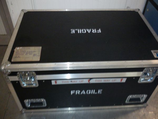
There are six shipping cases. Each box has a packing list taped to the inside of the lid. You will need to examine the packing lists and find the different components. The ULTRACAM packing cases consist of five flight cases and one wooden crate. The flight cases are all clearly marked ULTRACAM; the wooden crate has ULTRACAM written on it roughly in marker pen. Below is a picture of a typical flight case.
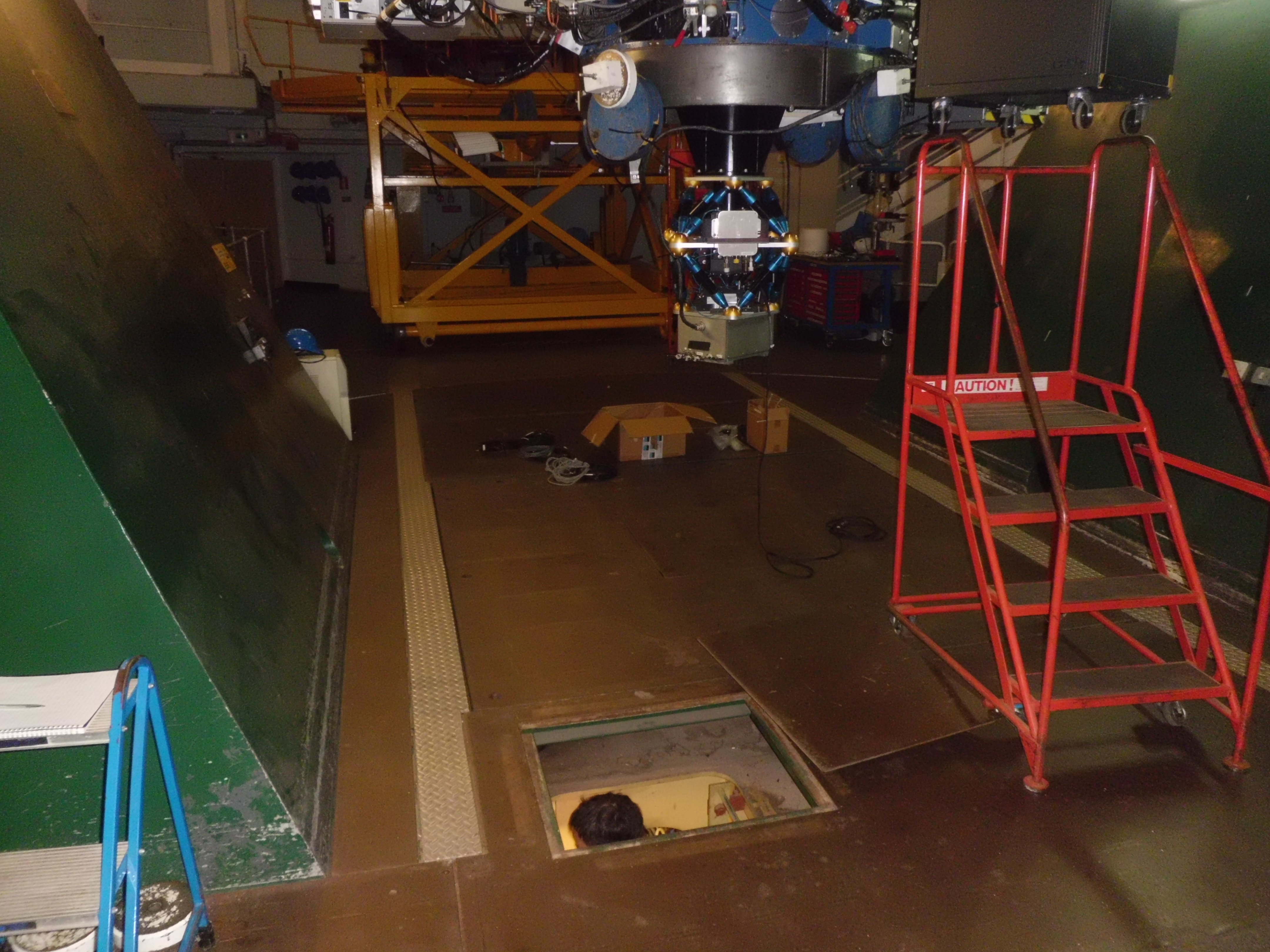
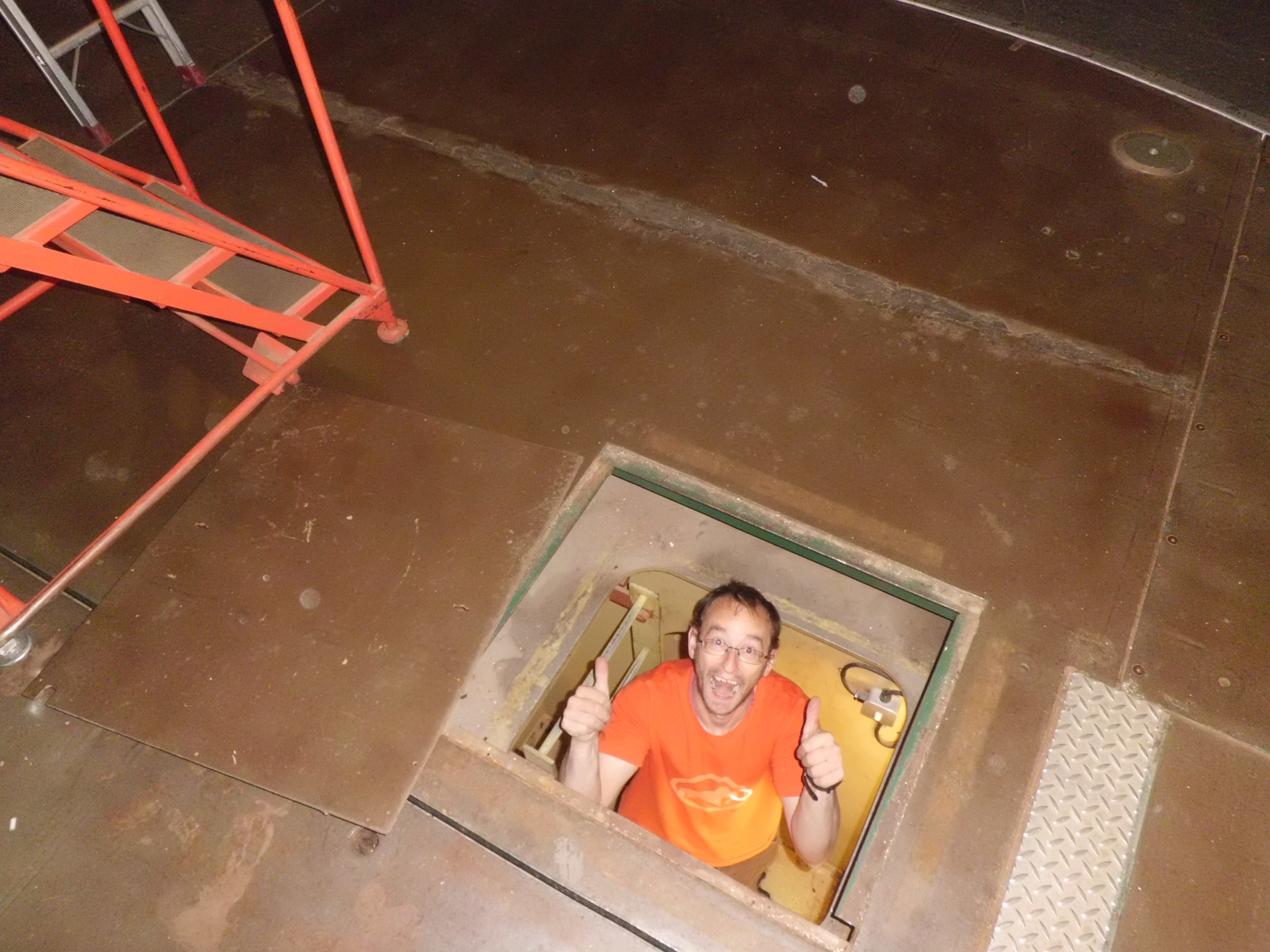
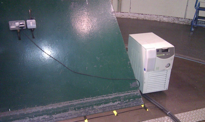
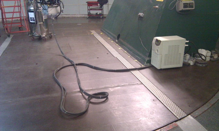
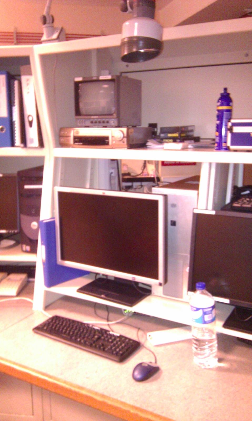
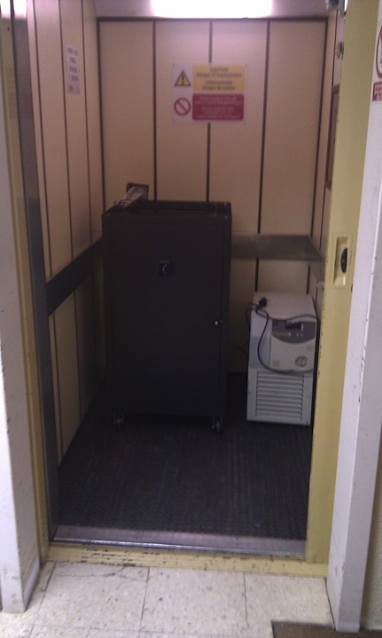
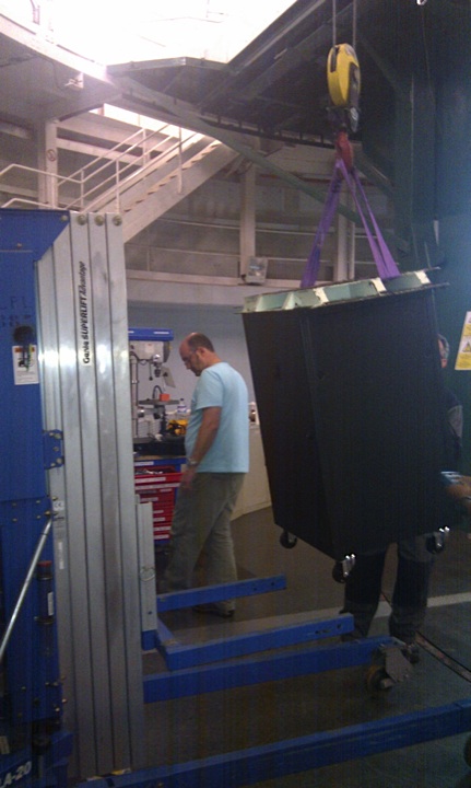
ULTRACAM, the rack, the focal plane slide and the water chiller should all be brought up to the observing floor with the help of the engineers. They will also need the black collar designed specifically for mounting onto the WHT. Other useful items include the bolts box, the toolbox, and the optics cleaning box. The lift can be used to move most things (see photo).
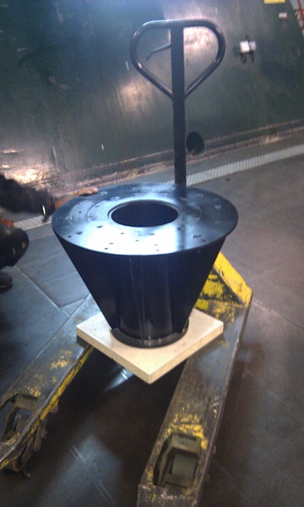
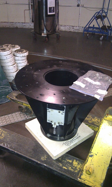
The mounting bracket, or collar, is show below.
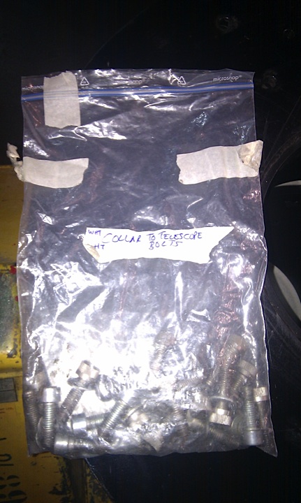
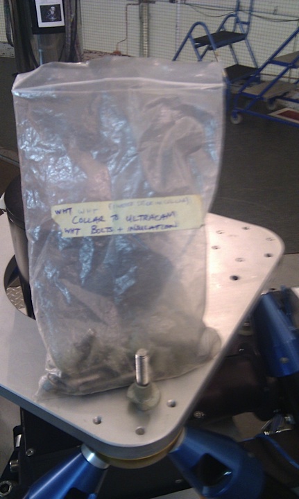
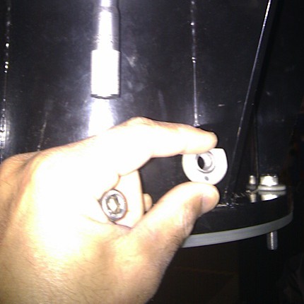
The engineers will mount the collar and the rack to the telescope, and the instrument to the collar. You should find the bolts for attaching the collar to the telescope and the instrument to the collar in the bolts box in one of the ULTRACAM crates. Examples of bolt bags are shown below. Do not tighten the bolts too hard into the aluminium body of ULTRACAM or you risk sheering off the threads.
The bolts for mounting the rack to the telescope are provided by the ING engineers, as the mounting plate belongs to them.
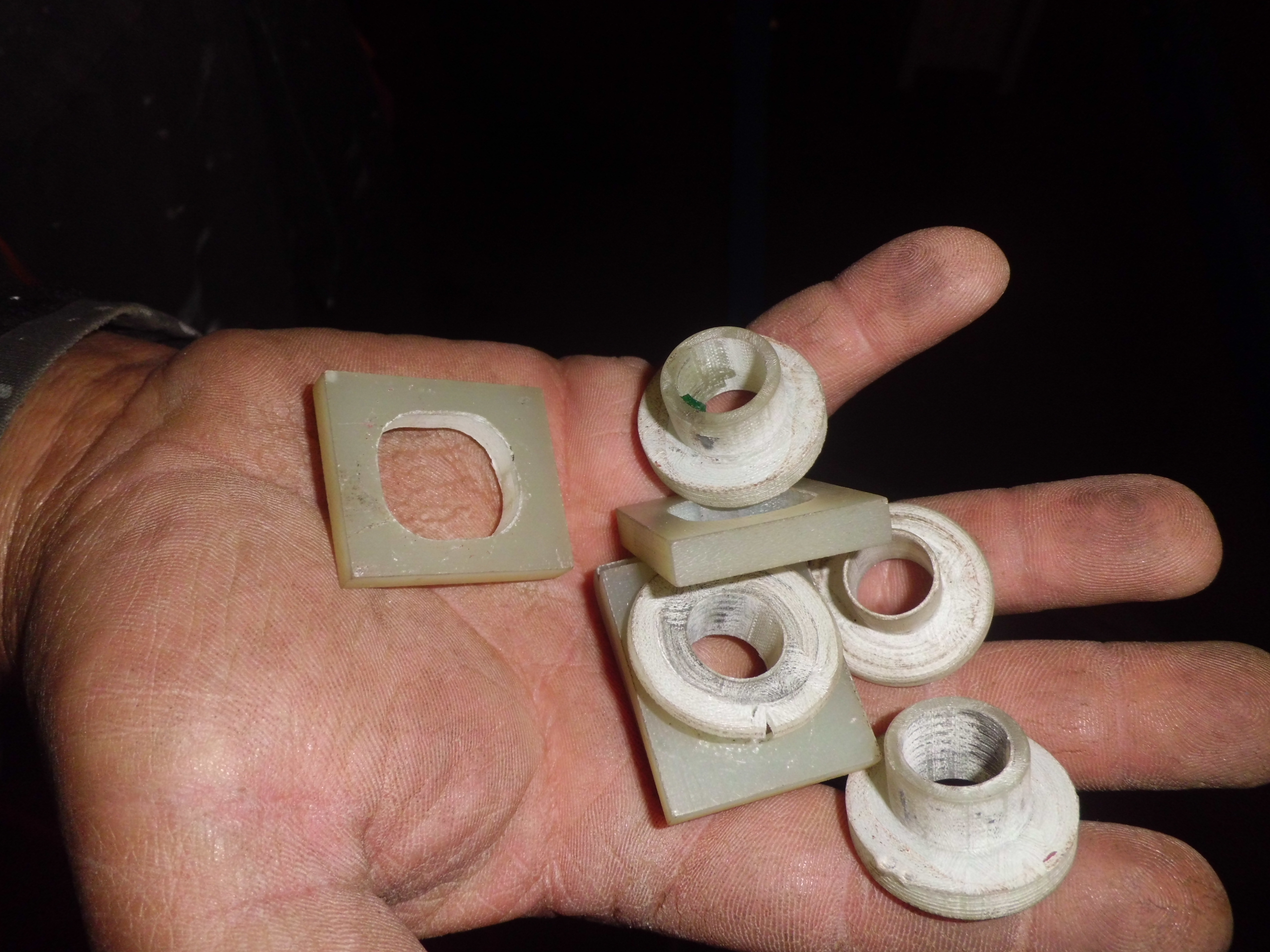
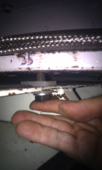
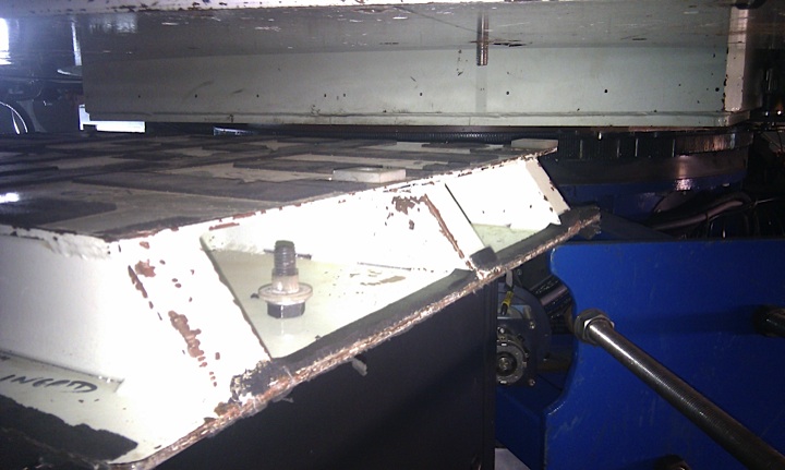
Ensure they use the insulating washers when mounting the rack and the instrument (see photos) - these should be found in the bolts box.
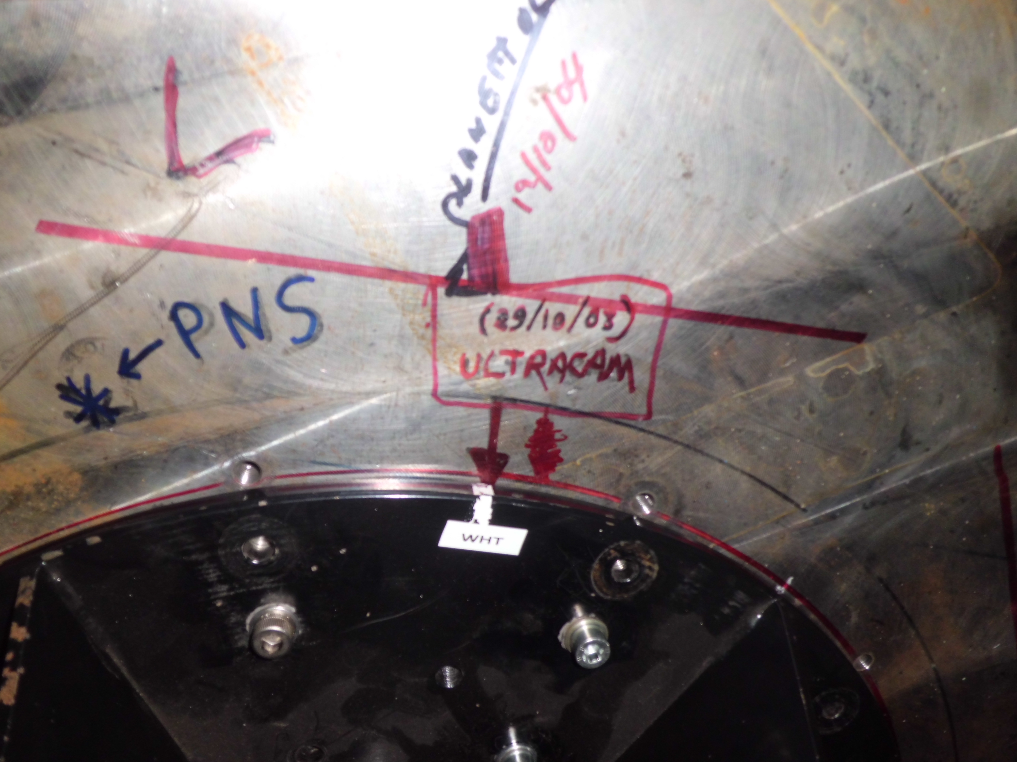
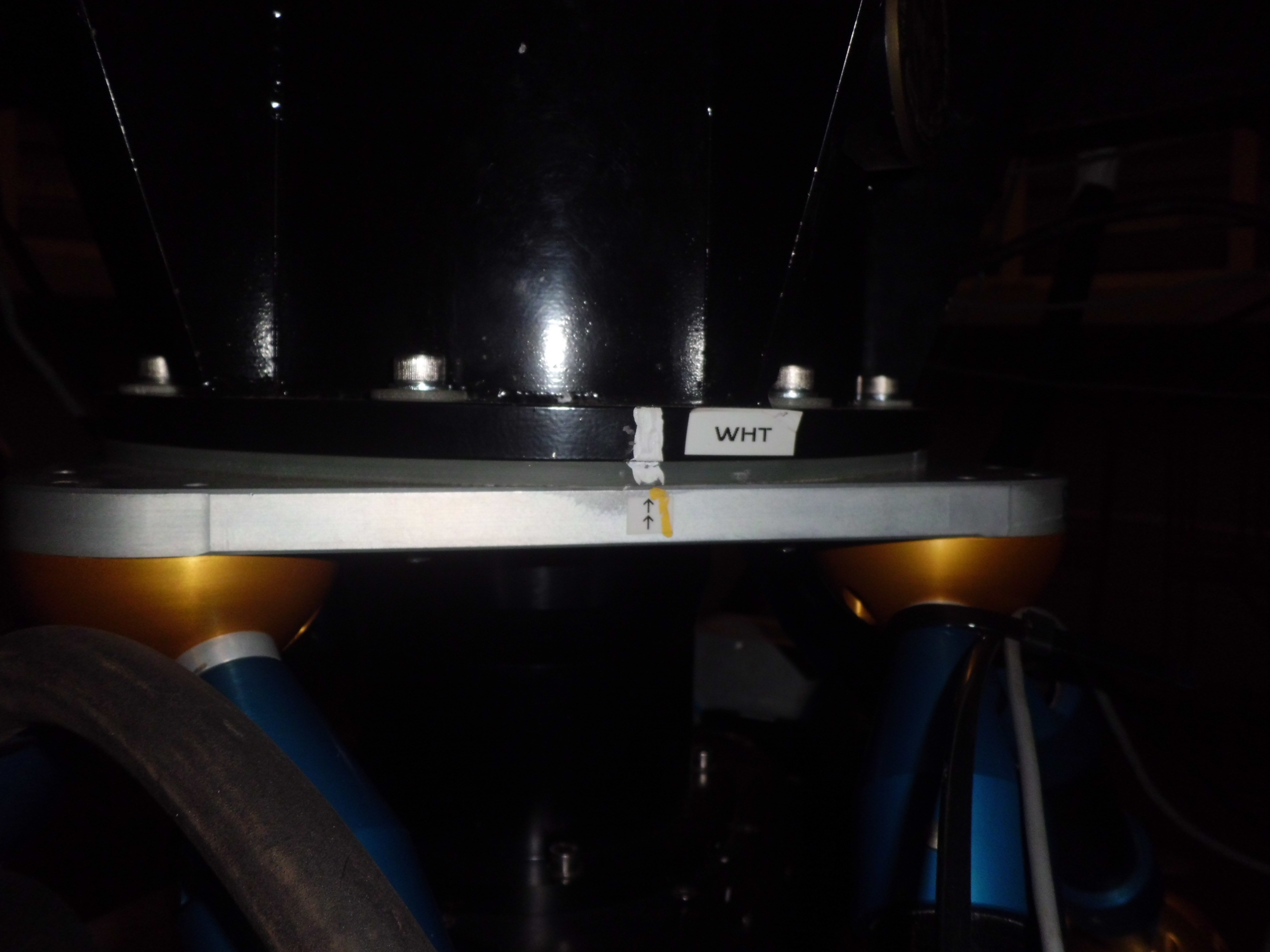
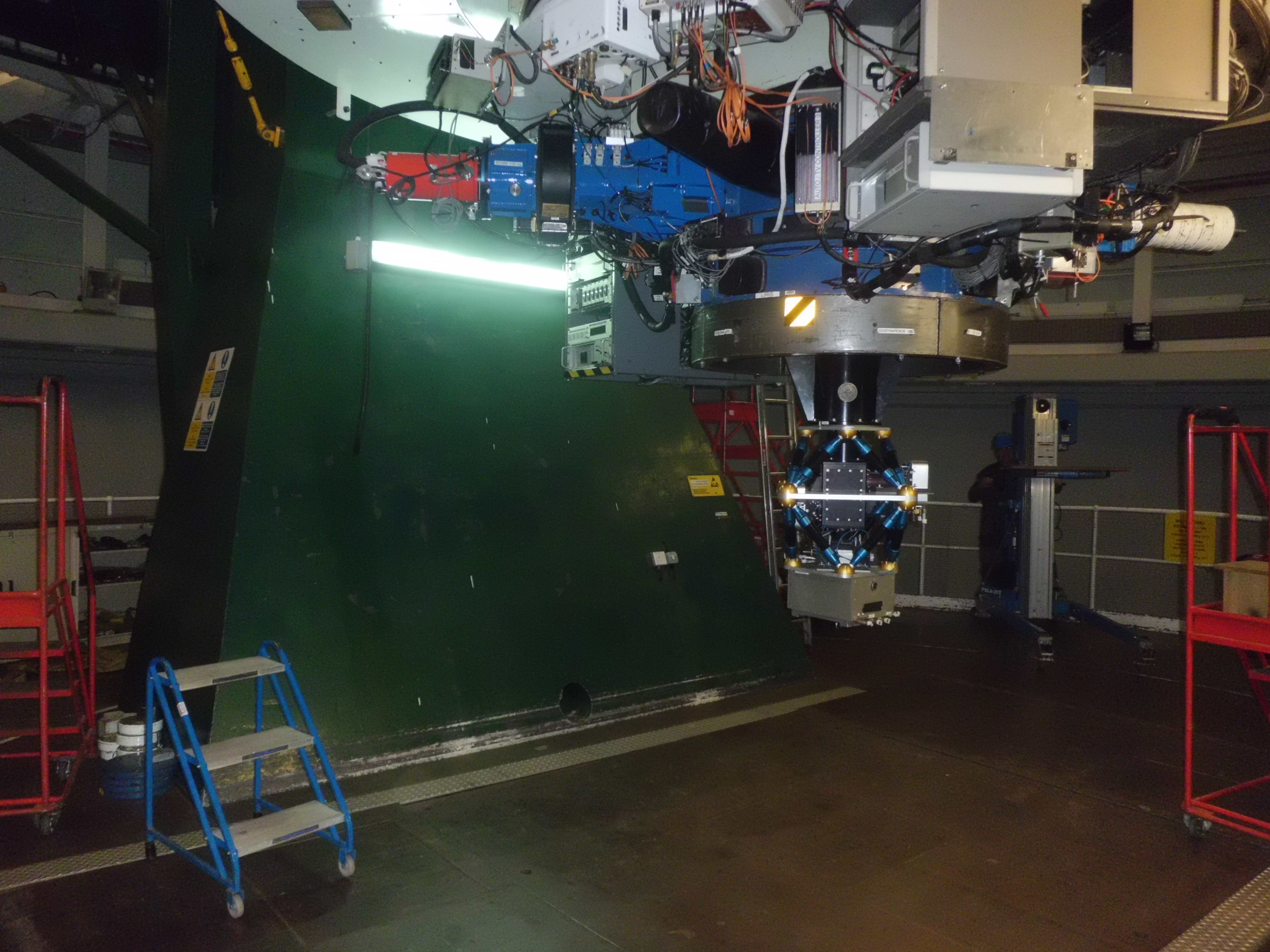
It is important that the collar is aligned such that the arrow on the aluminium top plate of ULTRACAM lines up with the corresponding arrow on the black collar. When the instrument is mounted, ensure it is also aligned correctly, with the focal plane slide bracket lining up with the gap in the telescope counter weights, and with the stickers matching up as shown in the figures below.
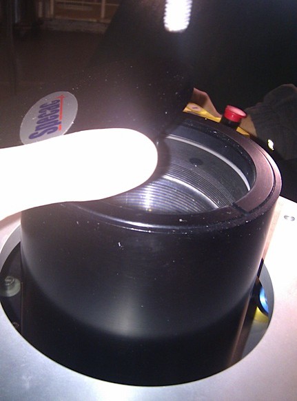
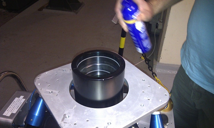
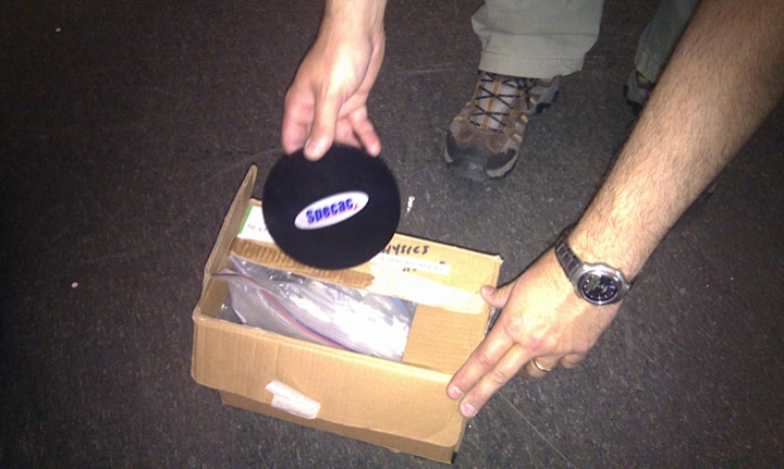
Before mounting the instrument to the collar, the lens cap should be removed, and cleared of any dust/debris using a clean air source. Spray cleaner should be used with care. Shake the can first, and always hold the can upright when spraying. Spray into the air or the back of your hand first in case there is some initial contamination in the nozzle or bottle.
Store the lenscap carefully in the bolts box.
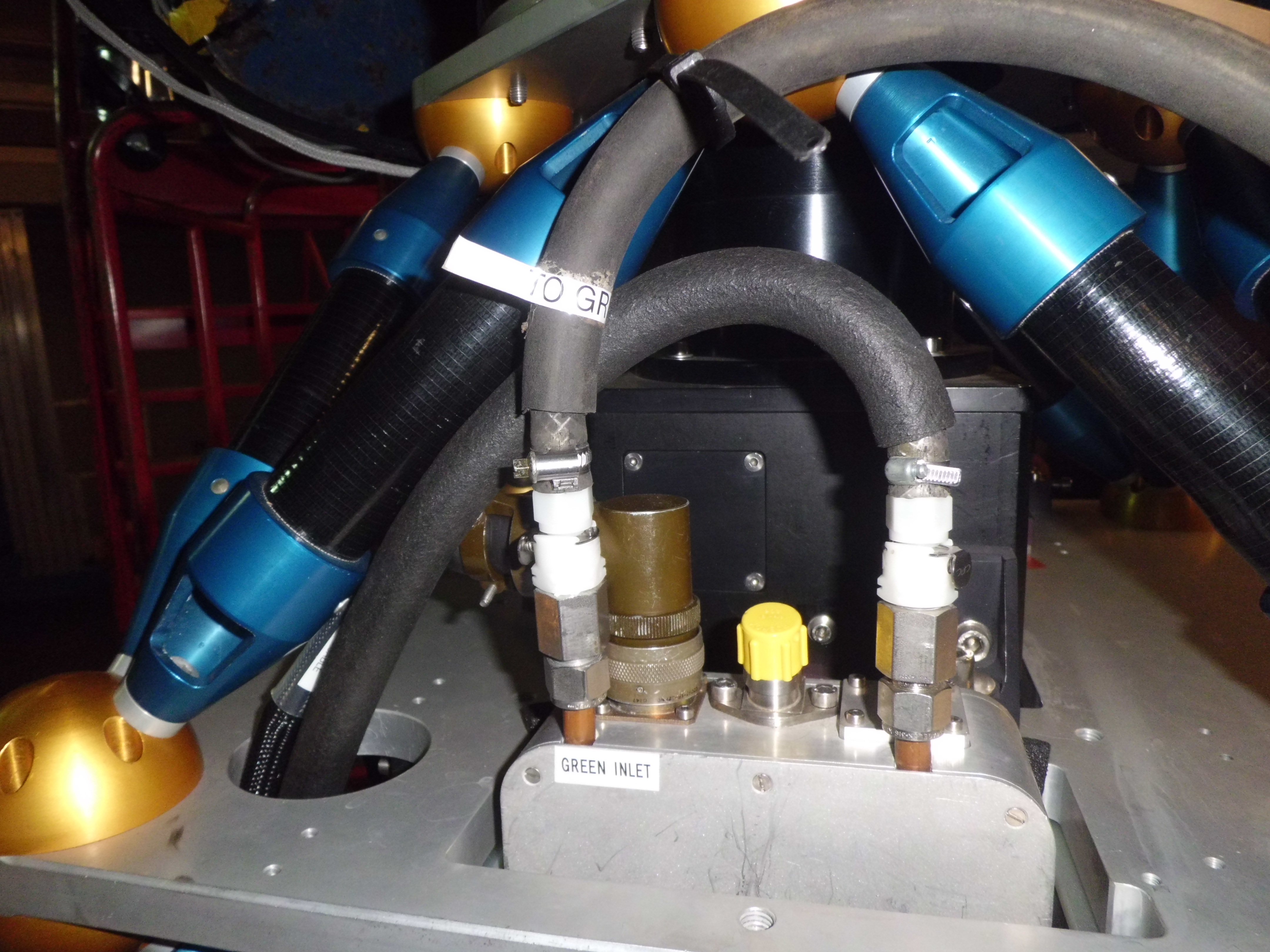
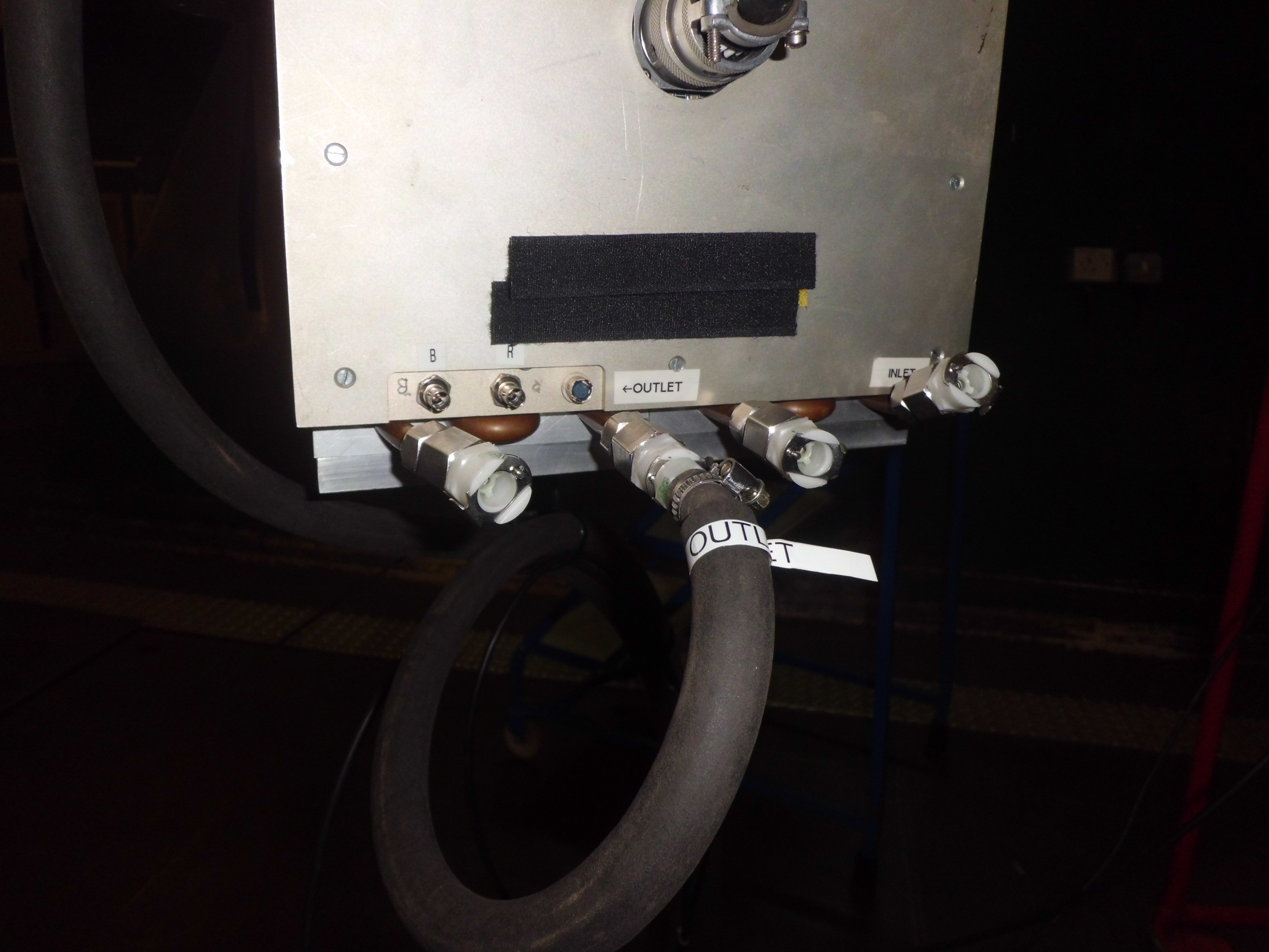
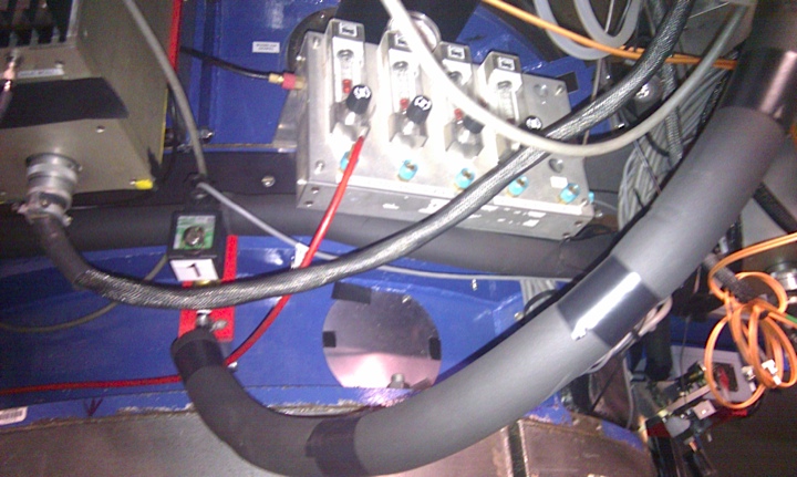
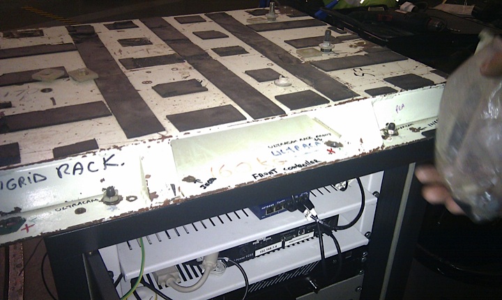
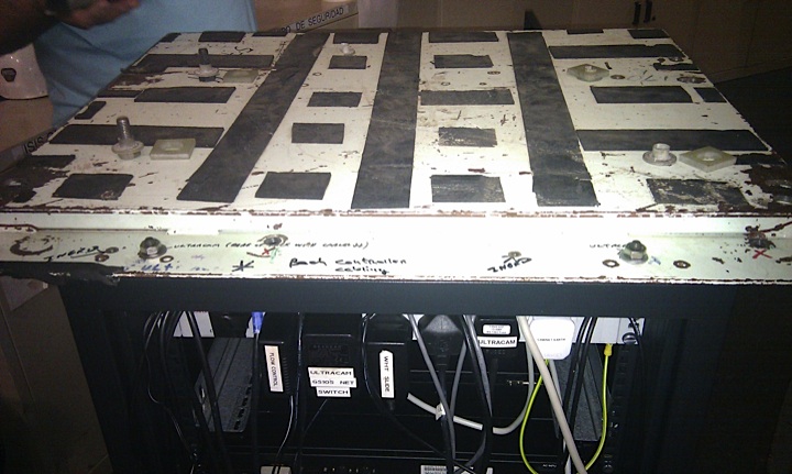
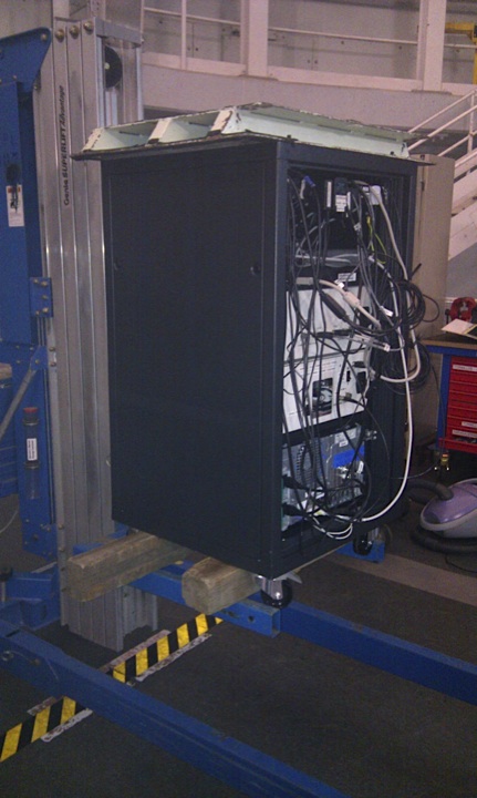
Mounting the rack with insulation between the mounting plate and the telescope. Make sure the ING's stainless-steel braided He pipes (shown in right-hand photo below) are not touching the top of the rack, as this could cause a ground loop and hence pickup noise in the detectors.
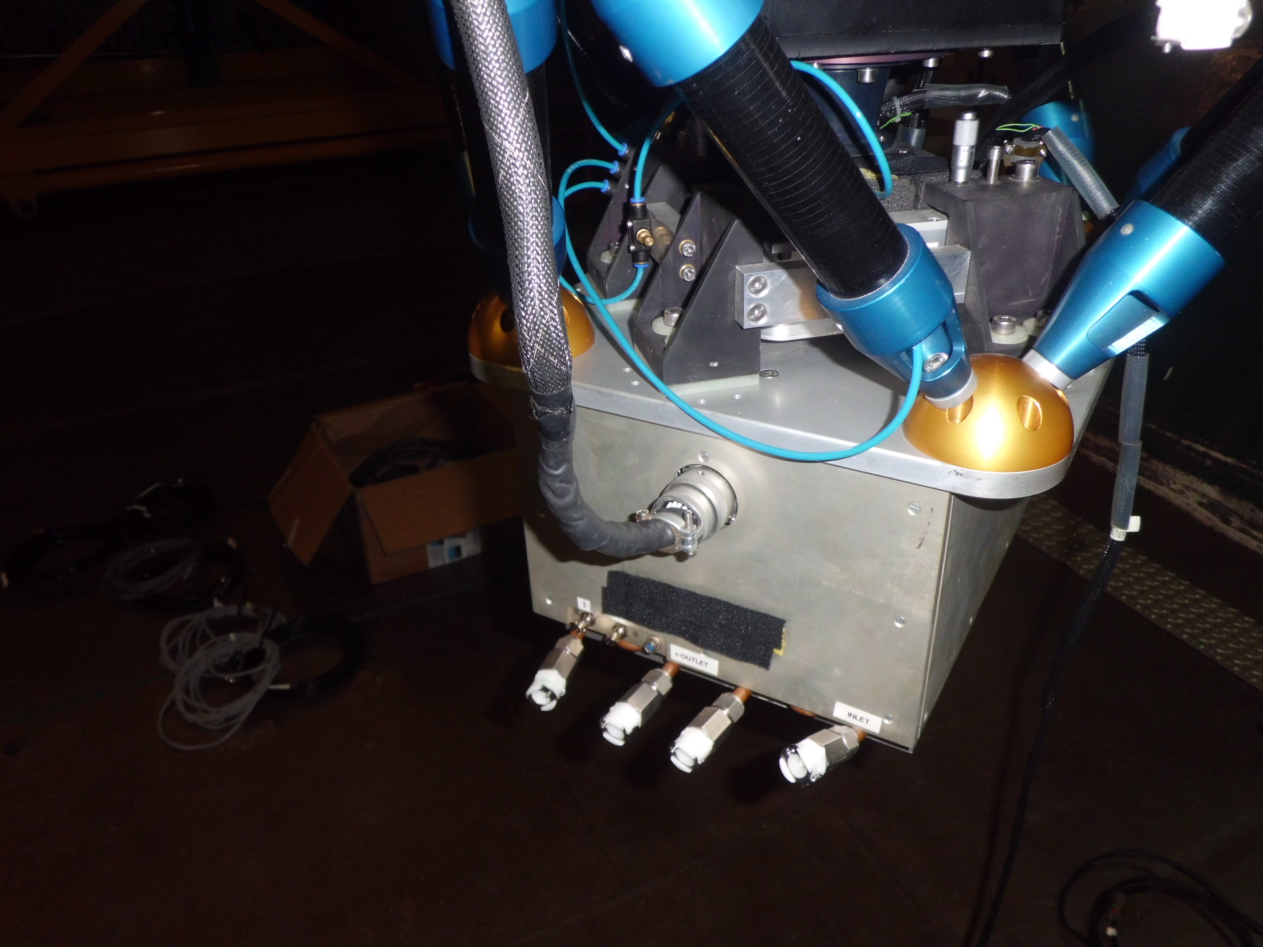
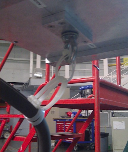
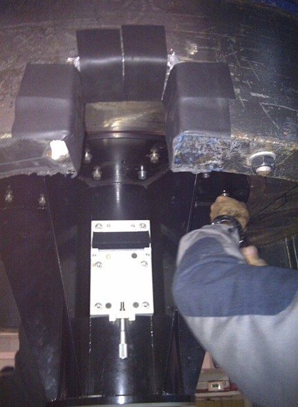
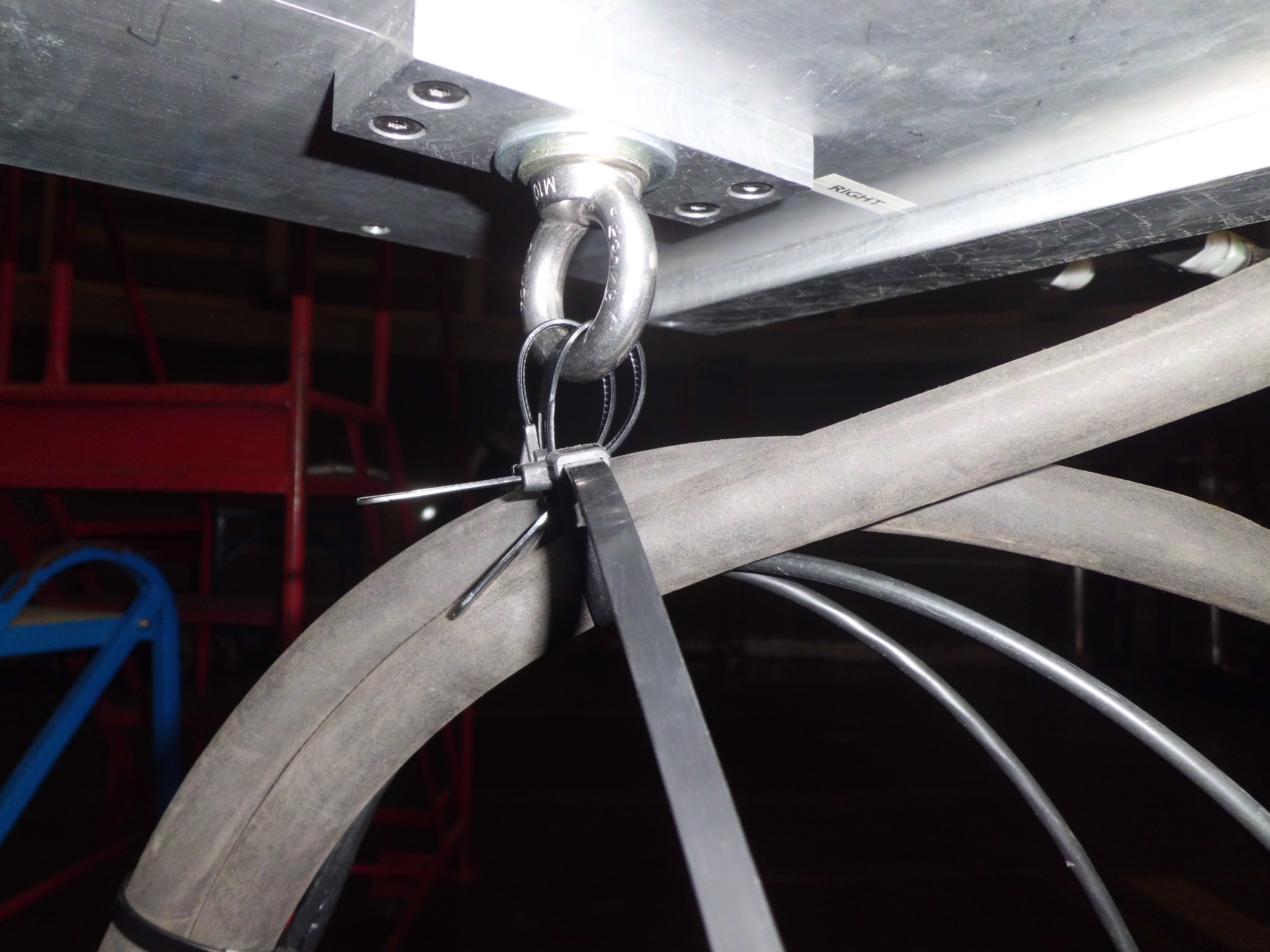
In the bolts box you should also find the 'cable twister', a strong steel hoop which screws into the underside of the SDSU controller on the bottom of ULTRACAM. This is used to hold the weight of the water hoses. Install this once the instrument is mounted.
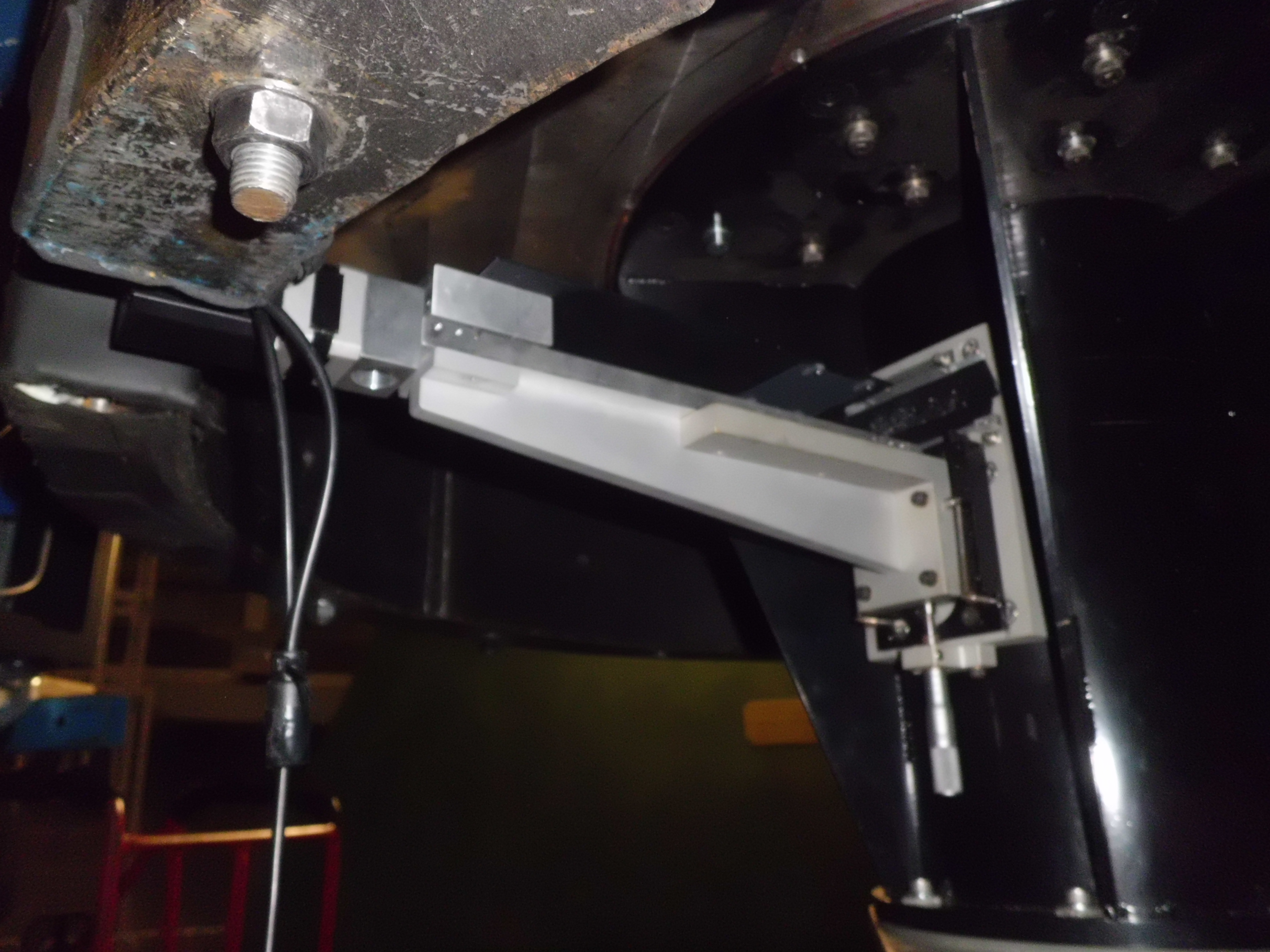
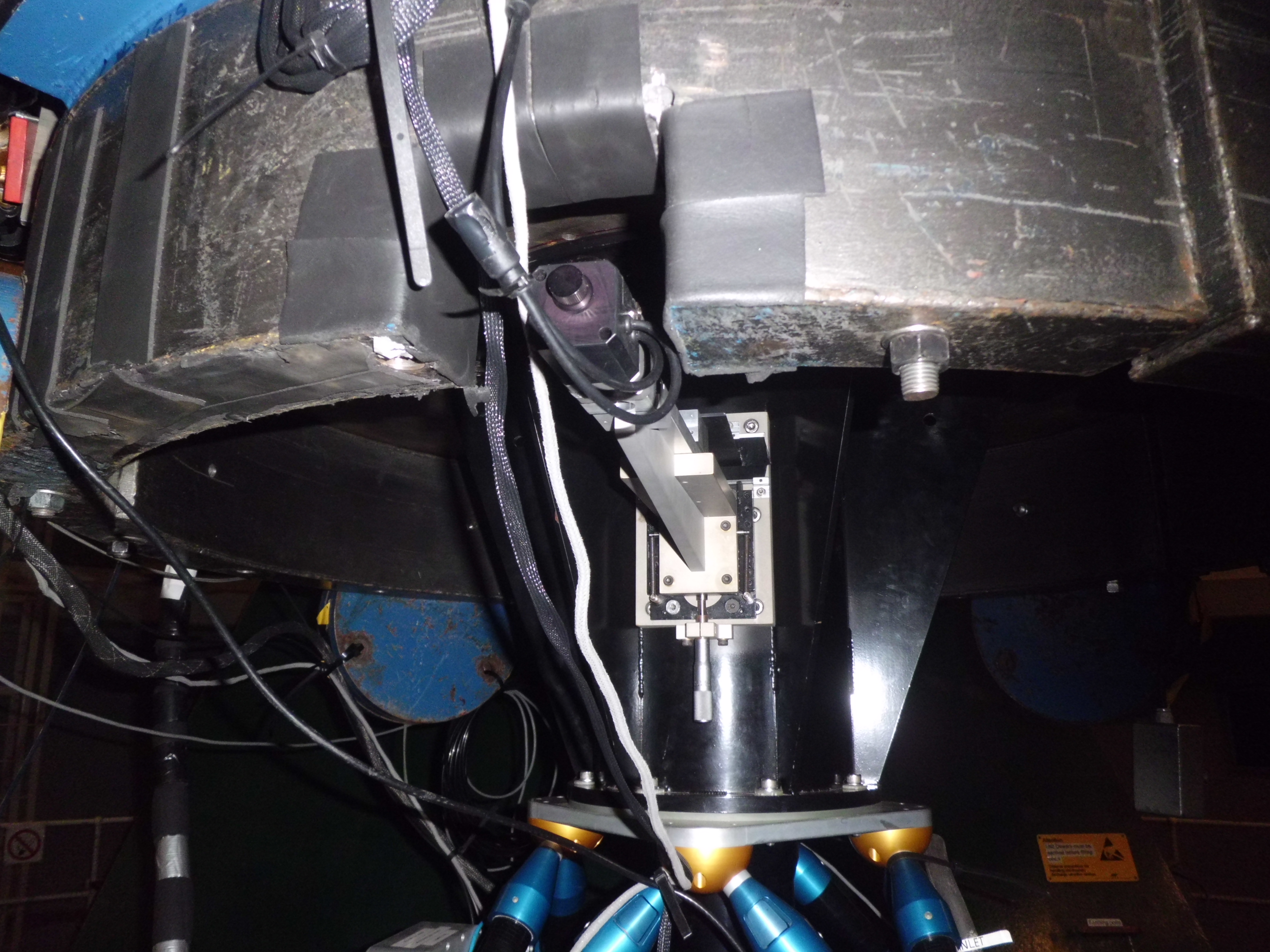
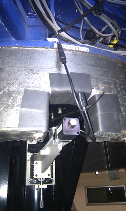
Next, mount the focal plane slide and bracket onto the side of the black mounting collar. Use the four small countersunk bolts, which should be found in the bolts box, if they are not already set in the focal plane bracket. The slide should slot through the gap cut through the telescope counter weights (see photos). This process can be quite tricky, as the slide bracket is spring loaded in the vertical direction. Once done, check that the micrometer is at its correct position (indicated on a sticker on the side of the bracket).
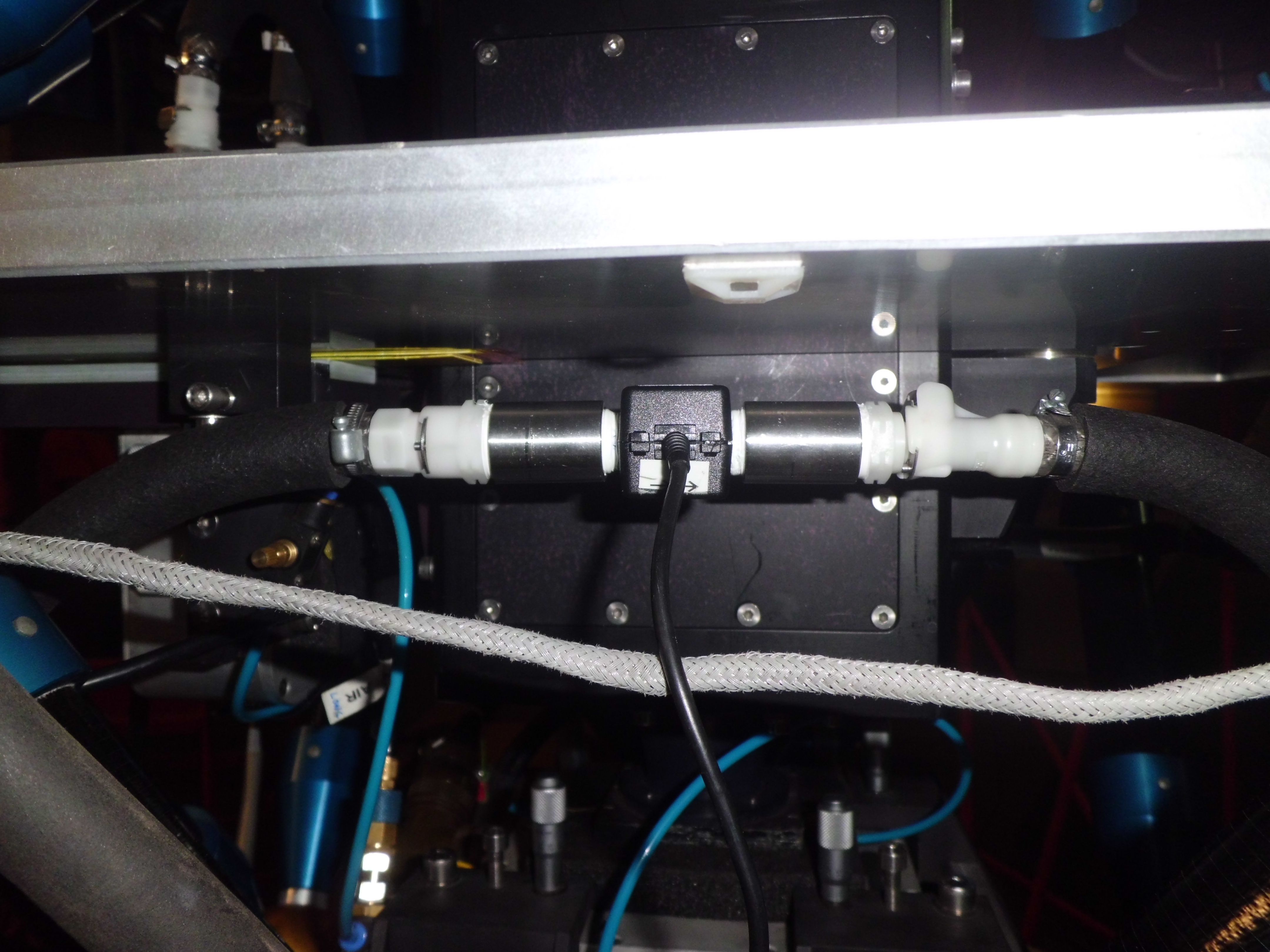
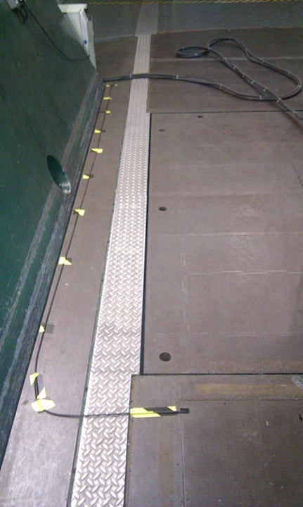
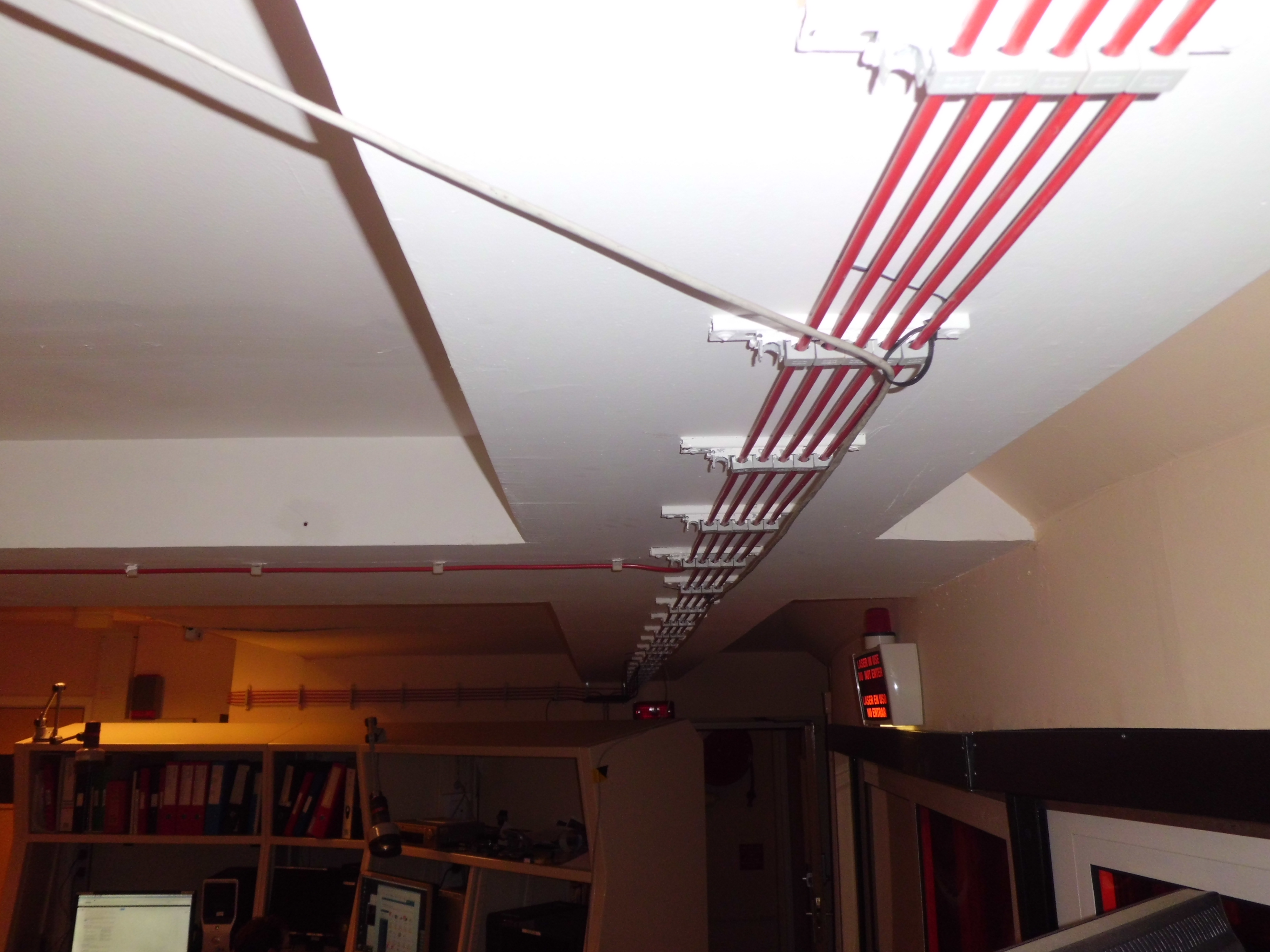
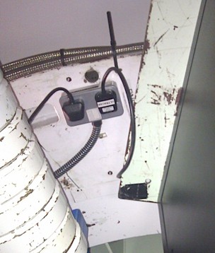
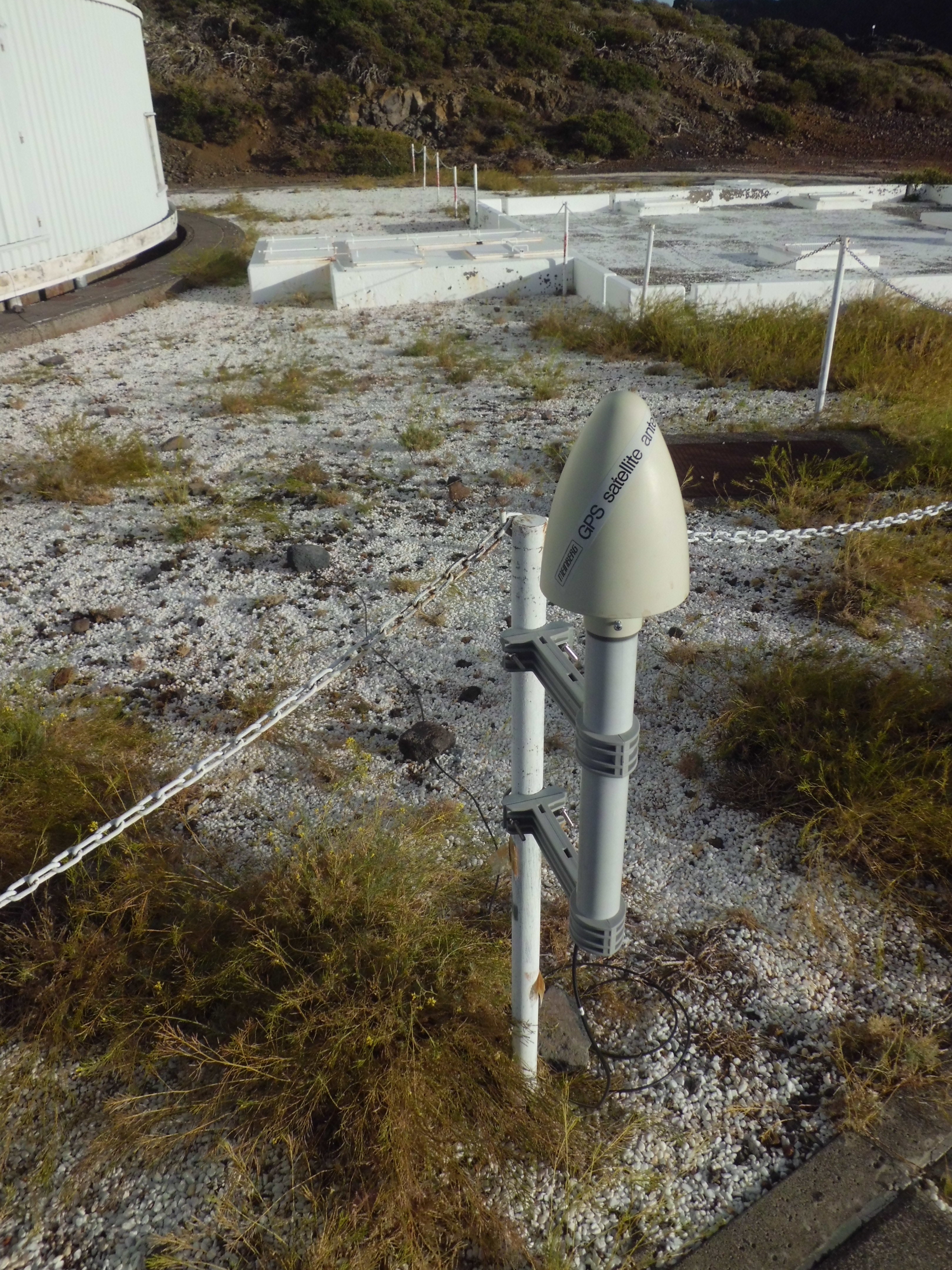
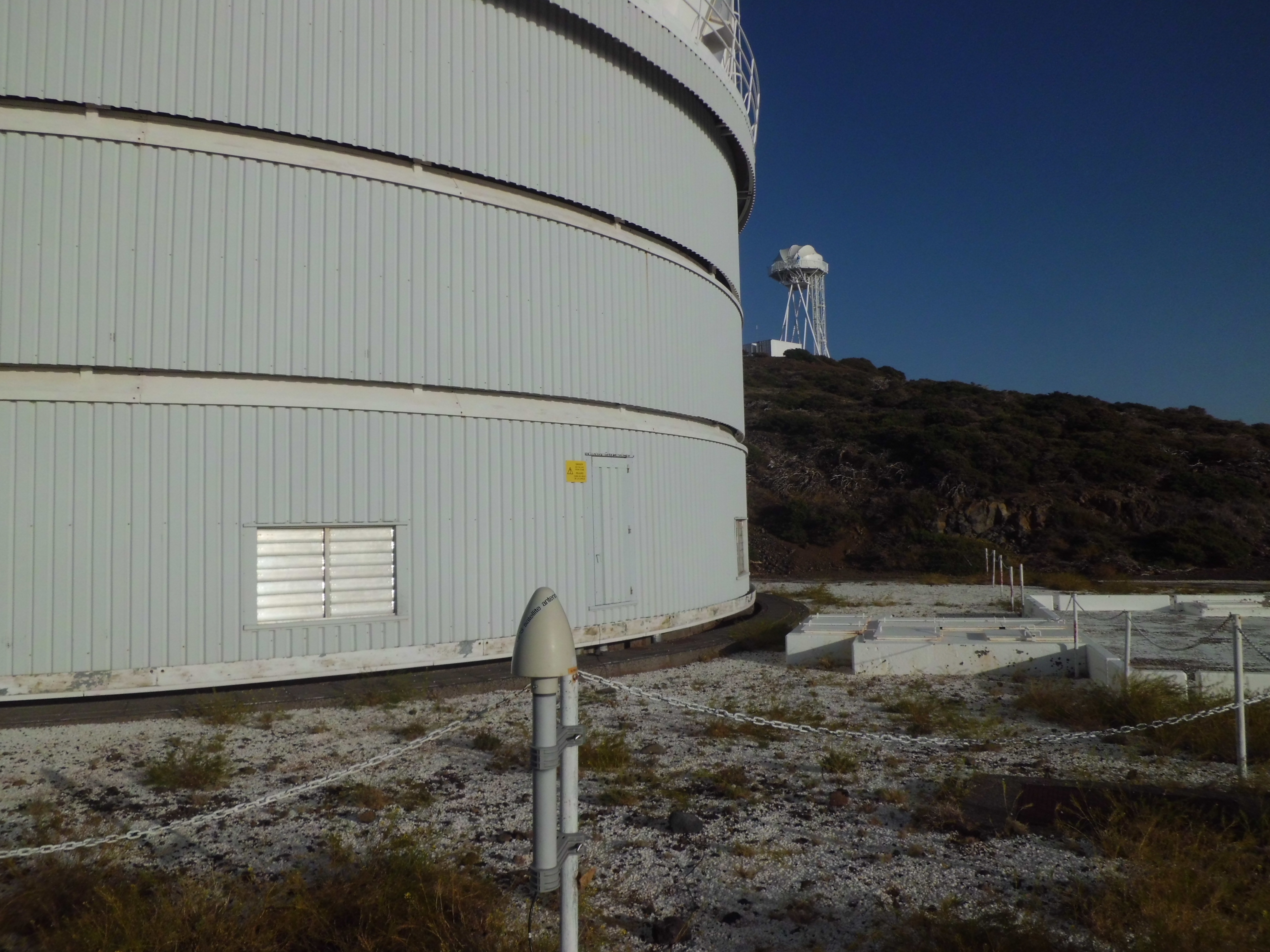
Set up the GPS antenna outside the dome, by attaching it to one of the posts on the North driveway. The GPS cable runs down through the azimuth cable twister, over the bridge near the East entrance on the ground floor of the dome, around the inside wall and out under the white metal sheeting on the outside of the dome. It is attached to the antenna by the aerial socket on the bottom - it is quite tricky to do this if you have big fingers and easy to fool yourself that the connector is attached when it actually isn't. Use flat rocks to anchor down the GPS cable, so that it cannot flap around in high winds.
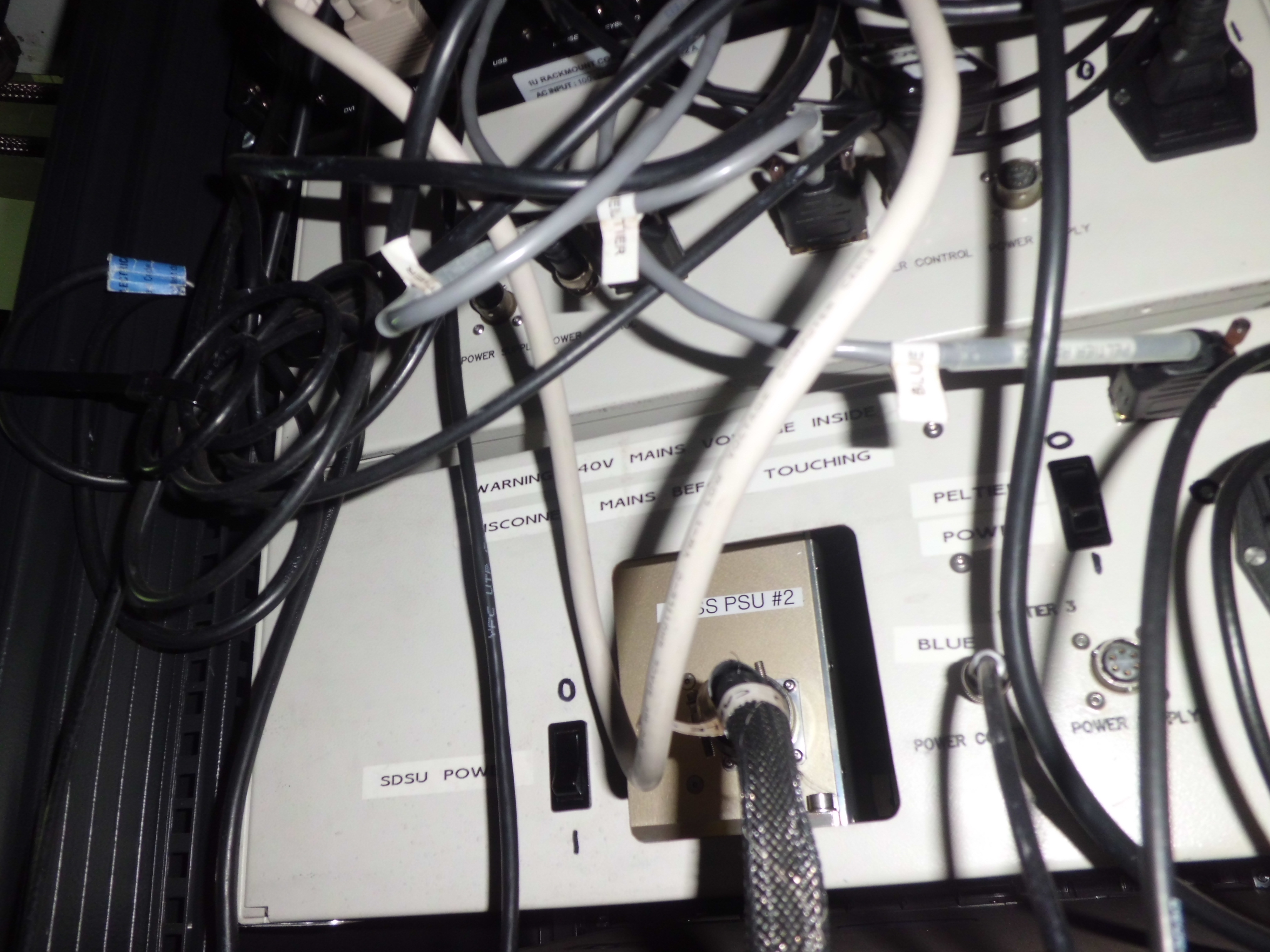
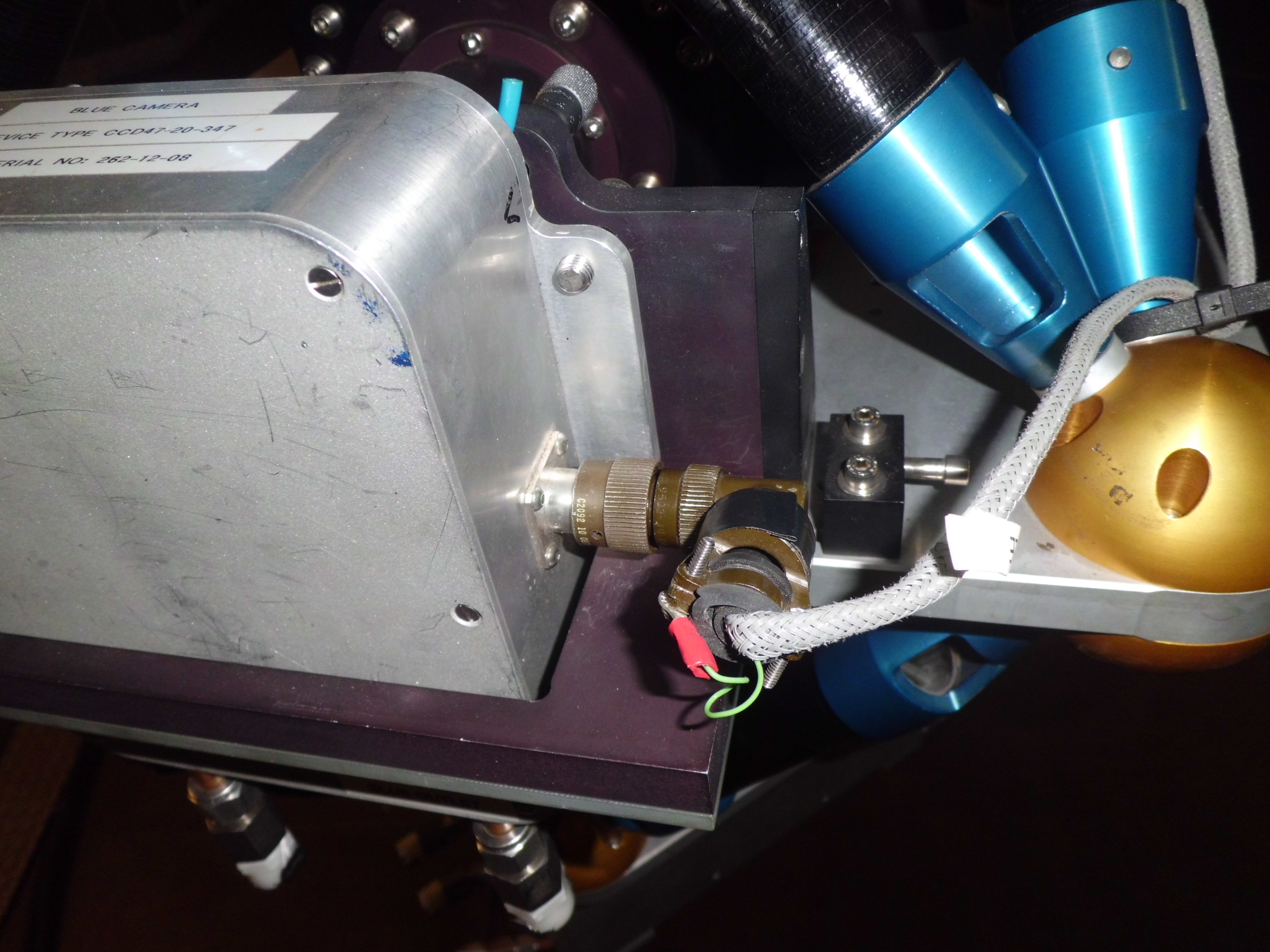
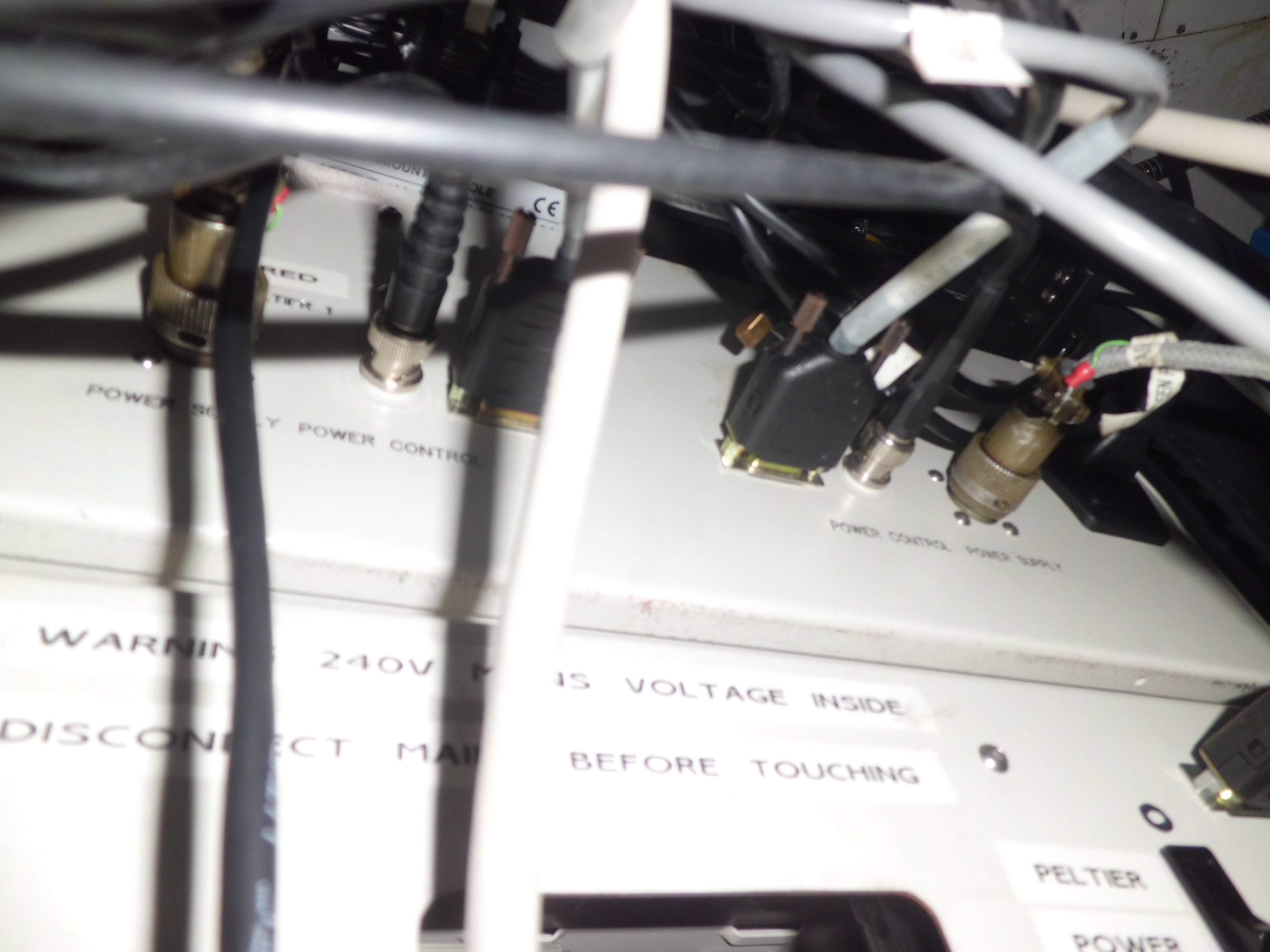
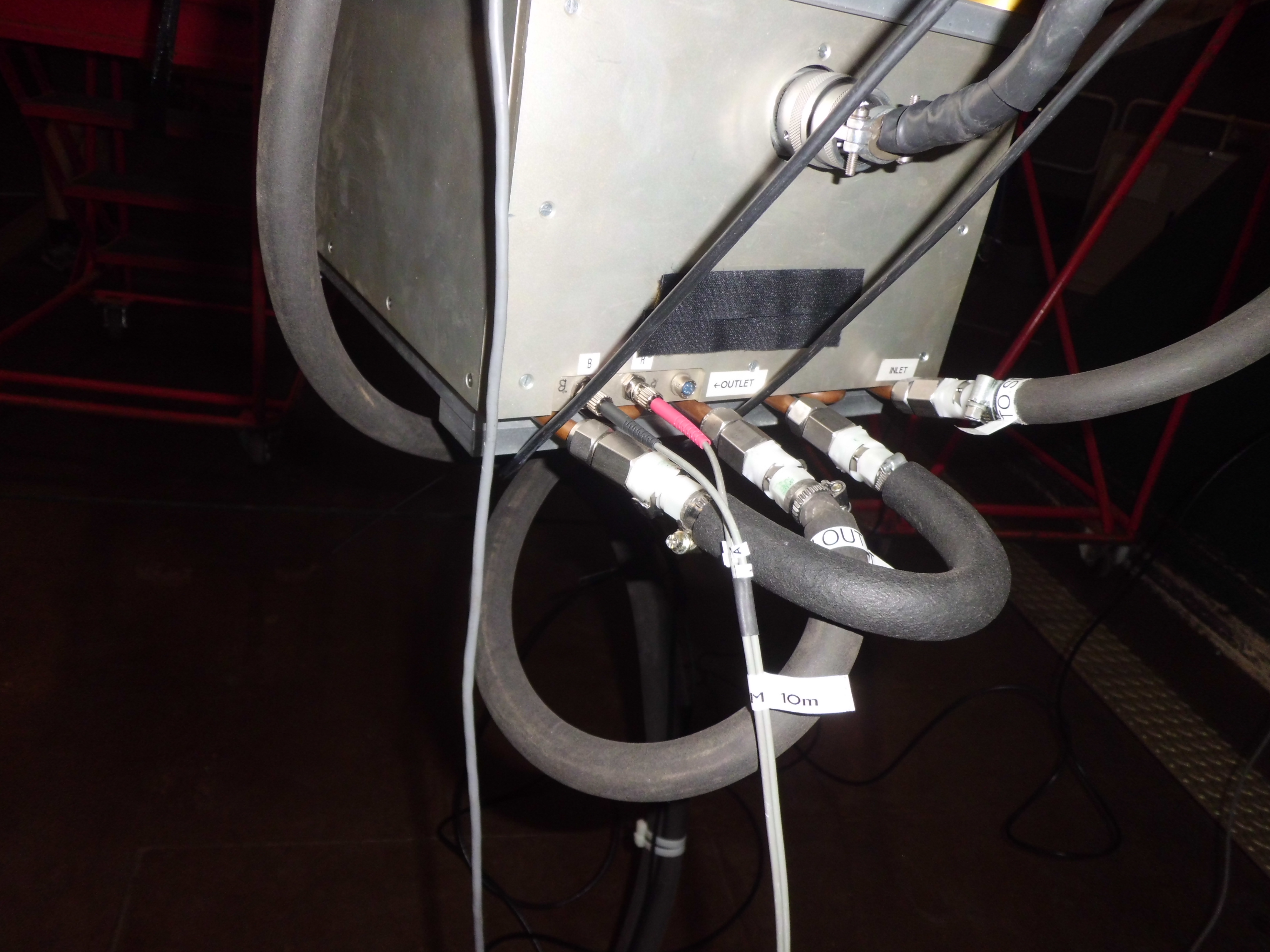
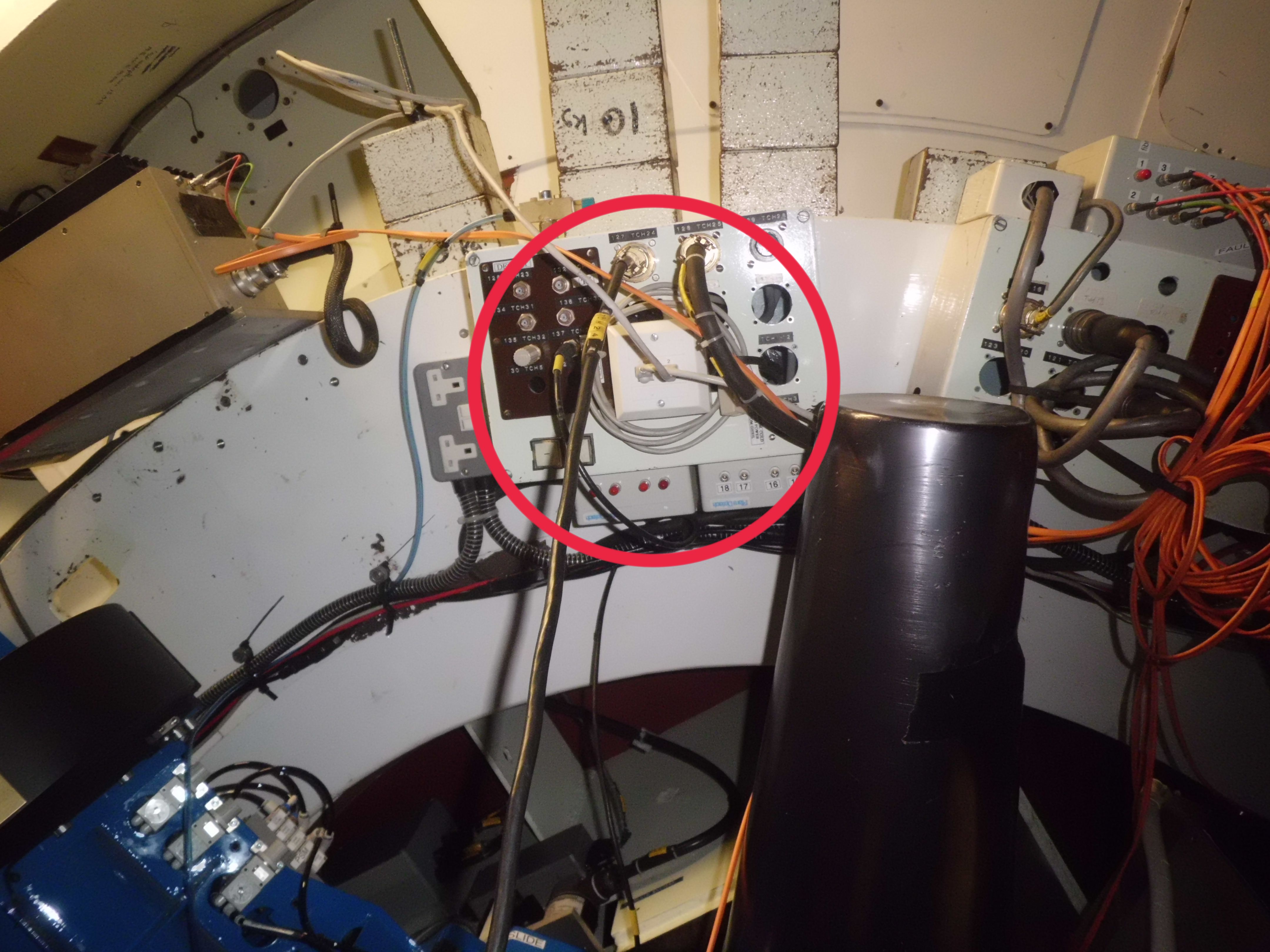
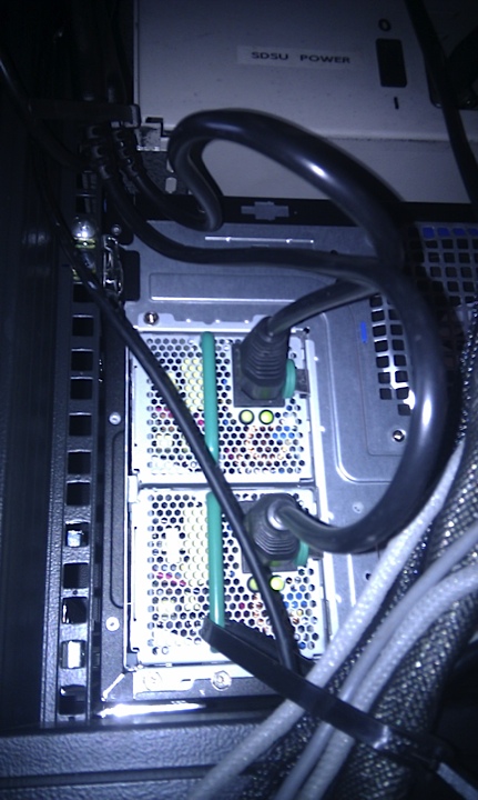
Cabling Up - the following cables must be attached carefully and without putting strain on connectors. Data cables and power cables should not pass close to each other if possible, to avoid pickup noise. In particular, avoid running any cables near the black video/bias cables running between the SDSU controller (from the end opposite the LED display) and each CCD head. Any loose cabling should be carefully secured so that it cannot flap around as the telescopes moves.