ULTRACAM is an ultra-fast, triple-beam photometer using the latest in Charge Coupled Device (CCD) technology, providing UK astronomers with the capability to do high-speed, multi-wavelength optical photometry1. The instrument will be assembled at the University of Sheffield, and the UKATC will deliver the detector system. It will be commissioned at the GHRIL focus of the 4.2m William Herschel Telescope (WHT) in La Palma for high temporal resolution investigation of interacting binary stars. It is anticipated that in addition to operation on the WHT it will also be utilised on other telescopes, such as the 2.5m Isaac Newton Telescope, 2-m Liverpool Telescope, 1.9m Radcliffe Telescope, and the 9.2m South African Large Telescope. Consequently, the instrument is required to be both portable and versatile.
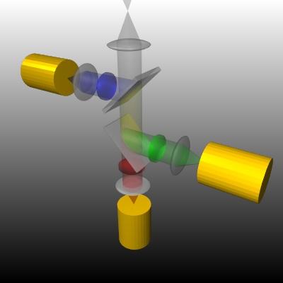
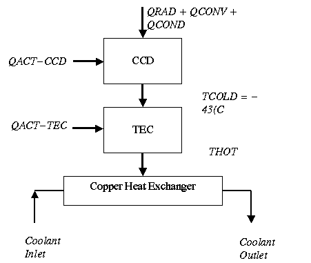
The optical design of the device includes collimating fore-optics to collimate the light from the telescope and two dichroic beamsplitters to split the light into blue, green, and red wavelengths, with each band of light filtered and re-focused onto a CCD chip, as illustrated in Figure 11. ULTRACAM will employ 3 frame-transfer CCD chips (MAT CCD47-20) to image a field of up to 5 arcminutes with essentially no dead-time simultaneously in three different colours. To minimise the influence of dark current, the CCD chips will be cooled using a multistage thermoelectric (TEC) device, adhered to a water-cooled copper heat exchanger. The desired dark current rate is 0.1electrons/pixel/second. This report is concerned with establishing the correct choice of TEC to obtain the desired dark current rates for the predicted thermal heat load.
Figure 1: ULTRACAM Optical Design
The desired dark current rate for ULTRACAM is 0.1electrons/pixel/second. The CCDs employed are Marconi Applied Technologies CCD47-20s (Backthinned), whose dark current rates are given by Equation 2.12.
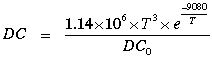 2.1
2.1
Where,
T = CCD Temperature in Kelvin
DC0 = Dark signal at 293K, specified as 250e/p/s typical or 500e/p/s worst case.
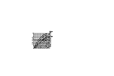
Assuming the worst case value for DC0 the dark current versus temperature curve is presented in Figure 2. Here it can be seen that a temperature of 233K is required for a dark current of less than 0.1e/p/s. Consequently, a desired device temperature of 230K will be adopted (0.05e/p/s).
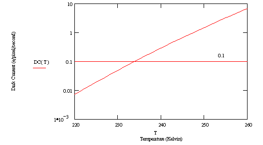
Figure 2: Dark Current versus Temperature for CCD47-20
The CCD is cooled using a TEC device, which are solid state heat pumps that utilise the Peltier effect. During operation, DC current flows through the TEC causing heat to be transferred from one of its sides to the other, creating a cold and hot side. The heat transferred to the hot side of the TEC will be dissipated via a water-cooled copper heat exchanger, as illustrated in Figure 3. The desired temperature for the TEC's cold side is 230K (-43°C).
Figure 3: CCD mounted on TEC and Heat Exchanger
To establish the desired TEC, its heat load and temperature difference characteristics must be established. The TEC's heat load can be established from Equation 3.13
![]() 3.1
3.1
Where,
QACT-CCD = Heat generated by CCD
QRAD = Radiative heat load
QCONV = Convective heat load
QCOND = Conductive heat load
Active Heat Load
CCD electrodes present a largely capacitive load. If the voltage across a capacitor C is pulsed with amplitude V at a frequency of f, then in each cycle a charge of CV is stored, and subsequently discharged to ground. The net current flow is thus CVf. Consequently the power dissipated is given by Equation 3.24.
![]() 3.2
3.2
V = 15volts
f = 500kHz (maximum)
C = 3.5nF (maximum)
Therefore, QACT-CCD = 0.39W
Radiative Heat Load
![]() 3.3
3.3
Where,
F = shape factor (1 worst case)
E = emissivity (1 worst case)
s = Stefan-Boltzmann Constant (5.66x10⁻⁸W/m2K4)
A = area of cooled surface (area of CCD: top + 4 sides)
= 0.0014m2 (CCD47-20)
TAMB = Ambient temp (K)
= 293K
TCOLD = TEC cold temp (K)
= 230K
Therefore, QRAD = 0.362W
Convective Heat Load
The convective heat load is given by Equation 3.43.
![]() 3.4
3.4
Where,
h = convective heat transfer
= 21.7W/m2°C
A = Surface area of CCD
= 0.0014m2
TAMB = 293K (worst case)
TCOLD = 230K
Therefore, QCONV = 1.914 W
Conductive Heat Load
For each conduction path to the CCD array (i.e. wires leading to CCD input pins) there will be a conduction path. There are 32 pins on the CCD47-20, and therefore the conductive heat load given is given by Equation 3.53.
![]() 3.5
3.5
Where,
k: Thermal conductivity of material (W/m °C)
A: cross sectional area of conductor
L: Length of conductor
DT: Temperature difference along heat path (TAMB - TCOLD)
Assuming, 32 gauge (radius=0.1mm) manganin wire of length 50mm leading from the PCB board to the camera head electrical input connectors.
k = 22.2 W/m °C
DT = 63°C
A = 1.571x10⁻⁸ m2
L = 50x10-3m
QCOND = 0.014W
Therefore, from Equation 3.1 it can be seen that:
QTEC-LOAD = 0.39W + 0.362W + 1.914W + 0.014W
= 2.684W
QTEC-LOAD = 3W
4. Thermal Performance of Heat Exchanger
The desired cold side temperature of the CCD is 230K (-43°C). Therefore, the hot side temperature needs to be estimated to calculate the required temperature difference. This is established by considering the copper heat exchanger's thermal characteristics. Consider the thermal flow diagram illustrated in Figure 4.
QTEC-LOAD
QEXC-LOAD
TCOOLANT:
Coolant Temperature
Figure 4: Thermal Flow Diagram
From Figure 4 it can be seen that the heat load on the copper heat exchanger is given by Equation 4.1.
QEXH-LOAD = QTEC-LOAD + QTEC-ACT 4.1
If a 2 stage TEC is employed and each stage is about 33% efficient (a reasonable assumption at this stage), then Equation 4.1 can be approximated to Equation 4.2.
QEXC = (100/33) x (100/33) x QTEC-LOAD 4.2
= 27W
Consequently, a water cooler that can reject at least 27W of heat from each of the three CCD heads, while maintaining a constant temperature is required. For example, the NESLAB M-255 can reject up to approximately 220W of heat while maintaining a minimum temperature of 5°C ± 0.1°C. Note that for a warmer temperature more heat can be rejected by the water cooler.
The heat exchanger used in ULTRACAM is a 5mm thick copper block with a channel milled into it to form a water path. The heat transfer capability of the copper Heat Exchanger is described by Equation 4.36. Where, U is the heat transfer constant (Equation 4.4), A is the characteristic area of the heat exchanger (area of the water channel), and DT is difference in temperature between the coolant and the hot side of the TEC (i.e. DT = THOT-TCOOLANT)
QEXC-LOAD = U x A x DT 4.3
Where,
 4.4
4.4
The designed heat exchanger has the following characteristics.
A = Characteristic area of copper perpendicular to heat flow
= 0.003 m2
h = Convective heat flow from copper to water
= 1500W/m2K
x = Characteristic path length through copper (depth through copper to coolant)
= 2x10⁻³m
k = Thermal conductivity of heat exchanger (i.e. copper)
= 400 W/mK
Note that 1/UA provides the heat exchanger's heat sink resistance (HSR), and in this case:
HSR = 0.224°C/W
If the NESLAB M-25, where employed as the recirculating chiller, then a minimum coolant temperature of 5°C could be achieved, however a coolant temperature of 10°C is assumed at this stage. Therefore,
TCOOLANT = 10°C,
Subsequently, since the system is required to reject 27W of heat (Estimate of QEXC-LOAD), the hot side temperature of TEC (THOT) can be estimated from Equation 4.3
 =
16°C
=
16°C
Therefore, with the assumption that the TEC is 33% efficient per stage, the following characteristics would be required to obtain a CCD cold side of -43°C:
TEC temperature difference of at least 59°C
TEC heat rejection of at least 3W
5. Determining the TEC Specification
When buying a TEC the manufacturers state the device's DTMax, and QMax. DTMax is the maximum temperature difference that the TEC can provide. This can only be achieved when there is no heat load. Conversely, QMax is the heat load that will reduce the device's temperature difference to zero. Therefore, for a given TEC the greater the heat load (i.e. closer to QMax), the lower the temperature difference that it can produce. Marlow Industries, Inc.3 provide a thermoelectric cooling systems design guide, which can be utilised to establish the TEC which best meets your system requirements.
Generally, in a dry nitrogen environment of 1 atmosphere (atm), the maximum temperature difference that can be achieved is 84°C with a two stage TEC, and is 95°C with a three stage TEC (note that greater temperature differences are specified for a vacuum environment). The ratio of the desired temperature difference and DTMax provides a device figure of merit. Therefore, since the required temperature difference for ULTRACAM has been shown to be 59°C the ratio DT to DTMax can be seen to be:
![]() 2-stage
TEC
2-stage
TEC
![]() 3-stage
TEC
3-stage
TEC
From
this figure of merit the required ratio of Q/QMax can be
determined using the TEC performance graph, see Figure 5 courtesy of
the Marlow Design Guide3. Here the performance graph
illustrates a DT to DTMax
ratio of 0.55. It can be seen that for this figure of merit
the optimum value of Q/QMax is 0.25 (i.e. where it
intersects the diagonal optimum line) and the maximum value of Q/QMax
is 0.45 (straight line through graph).
Figure 5: Marlow Industries Inc. TEC Performance Graph
Using Figure 5, the Q/QMax values required to meet ULTRACAM's specification can be established. Subsequently, the required QMax values, optimum and minimum, can be determined by dividing QTEC-LOAD (the heat load the TEC is required to reject i.e. 3W, see Section 2) by Q/QMax, optimum and maximum respectively. Table 1 summarises the relevant information.
|
|
2-Stage TEC |
3-Stage TEC |
|
DT/DTMax |
0.7 |
0.62 |
|
Optimum Q/QMax |
0.22 |
0.3 |
|
Maximum Q/QMax |
0.3 |
0.38 |
|
Optimum QMax |
13.6 |
10 |
|
Minimum QMax |
10 |
7.89 |
Table 1: Required QMax values of TEC
This data reveals that to meet ULTRACAM'S specification, (i.e. reject 3W of power and yield a temperature difference of 59°C) a 2-stage TEC with a QMax above 10W and optimally 13.6W, or a 3-stage TEC with a QMax above 7.89W and optimally 10W is required.
6. Off the Shelf TECs to meet Requirements
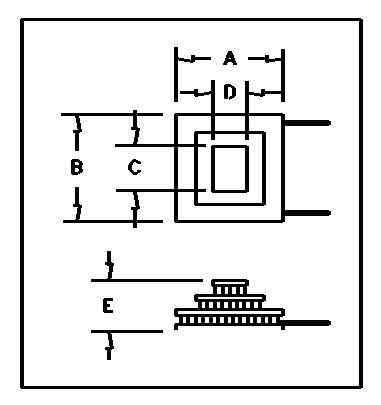
Standard Marlow and Melcor devices that best match the specified TEC requirements are outlined in Tables 2 and 3, with dimension diagrams provided in Figures 6 and 7. It should be noted that, with regard to this application there are no standard devices from these manufactures that out perform those detailed below.
Marlow
|
|
Model: |
M12064T(AB) |
M12063T(AB) |
|
|
Stage: |
2 |
3 |
|
THOT=27°C |
Tmax(Dry N2) °C: |
92 |
83 |
|
Qmax: |
9.6 |
14.0 |
|
|
Imax: |
5.6 |
5.0 |
|
|
Vmax: |
8.2 |
8.4 |
|
|
Dimensions |
Dim A (mm): |
29.6 |
29.6 |
|
Dim B (mm): |
29.6 |
29.6 |
|
|
Dim C (mm): |
13.0 |
19.6 |
|
|
Dim D (mm): |
13.0 |
19.6 |
|
|
Dim E (mm): |
7.4 |
7.4 |
|
|
|
Hot Tolerance ± mm: |
0.4 |
0.4 |
Melcor
Figure 7: Melcor TEC Dimensions
|
|
|
|
THOT=25°C |
Dimensions (mm) |
||||||
Catalogue Number |
Stage |
IMax (Amps) |
QMax (W) |
VMax (Volts) |
DTMax (°C) |
A |
B |
C |
D |
E |
|
2 CP 055 065-71-31 |
2 |
4.3 |
12.65 |
8.6 |
85 |
20 |
20 |
30 |
30 |
7.2 |
|
2.8 |
16.05 |
15.5 |
83 |
30 |
30 |
30 |
30 |
7.1 |
||
|
2 SC 040 050-127-63 |
10.3 |
30.22 |
8.6 |
85 |
30 |
30 |
44 |
44 |
8.9 |
|
|
6 |
34.51 |
15.5 |
83 |
40 |
40 |
40 |
40 |
7.5 |
||
|
2 CP 085 065-71-31 |
9.5 |
59.25 |
15.5 |
81 |
62 |
62 |
62 |
62 |
8.9 |
|
|
2 SC 055 045-127-63 |
||||||||||
|
2 SC 085 065-127-70 |
||||||||||
|
3 CP 055 065-127-71-31 |
3 |
3.5 |
12.58 |
15.4 |
96 |
20 |
20 |
40 |
40 |
10.4 |
|
8.4 |
15.6 |
7.7 |
97 |
22 |
22 |
44 |
44 |
12.9 |
||
|
3 CP 085 065-71-31-17 |
||||||||||
It can be seen that Melcor offer more TECs that meet the thermal requirements, and can provide a greater heat rejection. However, these devices are, in general, larger than the Marlow devices. It is envisaged that the CCD will be mounted directly on top of the TEC, and consequently the TEC's top lateral dimensions must be suitably small. The CCD47-20 has underside lateral dimensions of 42.0mm by 22.73mm. Therefore, the Marlow devices should have dimensions C and D less than this, and Table 2 reveals that they both do. On the other hand, the Melcor devices should have dimensions A and B less than this, and Table 3 illustrates that only models 2 CP 055 065-71-31, 3 CP 055 065-127-71-31, and 2 CP 085 065-71-31-17 demonstrate this. Therefore, there are five off-the-shelf TEC products available from these two manufacturers that meet the both the thermal and geometric specification. It should be noted that the device characteristics displayed in Tables 2 and 3 are specified for a specific hot side temperature. For Marlow this is THOT=27°C, while for Melcor it is THOT=25°C. In our case a THOT of 16°C is anticipated, therefore, the presented characteristics are not exact, nevertheless they do provide a pointer to the most suitable device.
7. Device Evaluation
The Marlow design guide was revisited to decide which of the five highlighted TEC devices is most suitable for this application. From the Marlow design guide's performance graphs, each of the device's minimum QMax and optimum QMax value were calculated. Furthermore, each TEC's current and voltage requirements for 59°C temperature difference and subsequent power consumption were estimated (note that 27W was previously assumed). The results are summarised below in Table 4:
|
Device |
1 |
2 |
3 |
4 |
5 |
|
Model |
M12064T (AB) |
M12063T (AB) |
2 CP 055 065-71-31 |
3 CP 055 065-127-71-31 |
3 CP 085 065-71-31-17 |
|
Manufacturer
|
Marlow |
Marlow |
Melcor |
Melcor |
Melcor |
|
Device DTMax (°C) |
92 |
83 |
85 |
96 |
97 |
|
Min. Required QMax (W) |
8.3 |
10.34 |
9.68 |
7.69 |
7.69 |
|
Optimum QMax (W) |
12.5 |
14.28 |
13.64 |
12.5 |
12.5 |
|
Device QMax (W) |
9.6 |
14 |
12.65 |
12.58 |
15.6 |
|
Device Efficiency w.r.t. Optimum QMax |
77% |
98% |
93% |
100.1% |
124.8% |
|
Required Current For DT=59°C (A) |
4.37 |
3.65 |
3.22 |
2.10 |
4.54 |
|
Required Voltage For DT=59°C (V) |
6.0®6.7 |
5.7®6.6 |
6.0®6.9 |
8.3®10.5 |
3.7®4.8 |
|
TEC Power Consumption (W) |
26.2®29.3 |
20.8®24.1 |
19.3®22.2 |
17.4®22.1 |
16.8®21.8 |
Table 4: Estimate of TECs Performance for Given Application Parameters
From the results presented in Table 4 it can be seen that device 2 is the preferred Marlow TEC, with a superior efficiency and lower power consumption. However, device 5 (3-stage Melcor TEC) has the best overall performance, displaying an efficiency of 124.8% with respect to optimum QMax, that is the ratio of the device's QMax to the optimum QMax. This means that device 5 could be driven harder to achieve a greater temperature difference and consequently lower CCD dark currents. In addition, its power consumption is the lowest of the presented devices, which will result in a lower THOT side than predicted in Section 4, and consequently a lower cold side for the same temperature difference. It is therefore proposed that the Melcor 3-stage TEC, model 3 CP 085 065-71-31-17, be employed as the ULTRACAM heat pump.
8. Conclusions
ULTRACAM demands low dark current rates, specifically less than 0.1e/pixel/sec. It has been show that to obtain this performance a CCD47-20 temperature of less than 233K is required. Consequently, the desired device temperature was stated as 230K, which would yield a dark current of 0.05e/pixel/sec. A TEC heat pump will be used to achieve this temperature, and in Section 3 it was revealed that the thermal load on such a device would be less than 3W. Moreover, Section 4 demonstrated that with the heat exchanger being used a temperature difference of 59°C would be required.
It was shown using Marlow Industries' design guide that in general a 2-stage TEC with a QMax above 10W and optimally 13.6W, or a 3-stagee TEC with a QMax above 7.89W and optimally 10W is required. In addition, the device's top-side lateral dimensions should be less than 22.7mm x 42.0mm so that it can be mounted directly to the underside of the CCD47-20. Marlow provide two off-the-shelf products that meet these specifications: M12064T(AB), and M12063T(AB), while Melcor provide three: 2 CP 055 065-71-31, 3 CP 055 065-127-71-31, and 3 CP 085 065-71-31-17. It was shown from subsequent analysis that the M12063T(AB) is the preferred Marlow device, however the Melcor 3 CP 085 065-71-31-17 provided the best theoretical performance, and is consequently proposed for this application. The only point of concern is that this device only just meets the geometric specification (top side lateral dimensions 22mm x 22mm), which may deem it unsuitable! The second choice device would be the Melcor 3 CP 055 065-127-71-31, or the Marlow M12063T(AB).
9. Feedback from manufactures
Marlow and Melcor have been contacted for cost quotes, and assistance on the best choice of TEC. Marlow responded quickly and have agreed that the M12063T(AB) is their most suitable product for our application. The cost is £176.00 per device.
Melcor have still to respond.
1 ULTRACAM Webpage: http://www.shef.ac.uk/uni/academic/N-Q/phys/people/vdhillon/ultracam/index.html
2 CCD47-20 Data Sheet, -height: 150%">The desired dark current rate for ULTRACAM is 0.1electrons/pixel/second. The CCDs employed are Marconi Applied Technologies CCD47-20s (Backthinned), whose dark current rates are given by Equation 2.12.
2.1
Where,
T = CCD Temperature in Kelvin
DC0 = Dark signal at 293K, specified as 250e/p/s typical or 500e/p/s worst case.
Assuming the worst case value for DC0 the dark current versus temperature curve is presented in Figure 2. Here it can be seen that a temperature of 233K is required for a dark current of less than 0.1e/p/s. Consequently, a desired device temperature of 230K will be adopted (0.05e/p/s).
Figure 2: Dark Current versus Temperature for CCD47-20
The CCD is cooled using a TEC device, which are solid state heat pumps that utilise the Peltier effect. During operation, DC current flows through the TEC causing heat to be transferred from one of its sides to the other, creating a cold and hot side. The heat transferred to the hot side of the TEC will be dissipated via a water-cooled copper heat exchanger, as illustrated in Figure 3. The desired temperature for the TEC's cold side is 230K (-43°C).
Figure 3: CCD mounted on TEC and Heat Exchanger
To establish the desired TEC, its heat load and temperature difference characteristics must be established. The TEC's heat load can be established from Equation 3.13
![]() 3.1
3.1
Where,
QACT-CCD = Heat generated by CCD
QRAD = Radiative heat load
QCONV = Convective heat load
QCOND = Conductive heat load
Active Heat Load
CCD electrodes present a largely capacitive load. If the voltage across a capacitor C is pulsed with amplitude V at a frequency of f, then in each cycle a charge of CV is stored, and subsequently discharged to ground. The net current flow is thus CVf. Consequently the power dissipated is given by Equation 3.24.
![]() 3.2
3.2
V = 15volts
f = 500kHz (maximum)
C = 3.5nF (maximum)
Therefore, QACT-CCD = 0.39W
Radiative Heat Load
![]() 3.3
3.3
Where,
F = shape factor (1 worst case)
E = emissivity (1 worst case)
s = Stefan-Boltzmann Constant (5.66x10⁻⁸W/m2K4)
A = area of cooled surface (area of CCD: top + 4 sides)
= 0.0014m2 (CCD47-20)
TAMB = Ambient temp (K)
= 293K
TCOLD = TEC cold temp (K)
= 230K
Therefore, QRAD = 0.362W
Convective Heat Load
The convective heat load is given by Equation 3.43.
![]() 3.4
3.4
Where,
h = convective heat transfer
= 21.7W/m2°C
A = Surface area of CCD
= 0.0014m2
TAMB = 293K (worst case)
TCOLD = 230K
Therefore, QCONV = 1.914 W
Conductive Heat Load
For each conduction path to the CCD array (i.e. wires leading to CCD input pins) there will be a conduction path. There are 32 pins on the CCD47-20, and therefore the conductive heat load given is given by Equation 3.53.
![]() 3.5
3.5
Where,
k: Thermal conductivity of material (W/m °C)
A: cross sectional area of conductor
L: Length of conductor
DT: Temperature difference along heat path (TAMB - TCOLD)
Assuming, 32 gauge (radius=0.1mm) manganin wire of length 50mm leading from the PCB board to the camera head electrical input connectors.
k = 22.2 W/m °C
DT = 63°C
A = 1.571x10⁻⁸ m2
L = 50x10-3m
QCOND = 0.014W
Therefore, from Equation 3.1 it can be seen that:
QTEC-LOAD = 0.39W + 0.362W + 1.914W + 0.014W
= 2.684W
QTEC-LOAD = 3W
4. Thermal Performance of Heat Exchanger
The desired cold side temperature of the CCD is 230K (-43°C). Therefore, the hot side temperature needs to be estimated to calculate the required temperature difference. This is established by considering the copper heat exchanger's thermal characteristics. Consider the thermal flow diagram illustrated in Figure 4.
QTEC-LOAD
QEXC-LOAD
TCOOLANT:
Coolant Temperature
Figure 4: Thermal Flow Diagram
From Figure 4 it can be seen that the heat load on the copper heat exchanger is given by Equation 4.1.
QEXH-LOAD = QTEC-LOAD + QTEC-ACT 4.1
If a 2 stage TEC is employed and each stage is about 33% efficient (a reasonable assumption at this stage), then Equation 4.1 can be approximated to Equation 4.2.
QEXC = (100/33) x (100/33) x QTEC-LOAD 4.2
= 27W
Consequently, a water cooler that can reject at least 27W of heat from each of the three CCD heads, while maintaining a constant temperature is required. For example, the NESLAB M-255 can reject up to approximately 220W of heat while maintaining a minimum temperature of 5°C ± 0.1°C. Note that for a warmer temperature more heat can be rejected by the water cooler.
The heat exchanger used in ULTRACAM is a 5mm thick copper block with a channel milled into it to form a water path. The heat transfer capability of the copper Heat Exchanger is described by Equation 4.36. Where, U is the heat transfer constant (Equation 4.4), A is the characteristic area of the heat exchanger (area of the water channel), and DT is difference in temperature between the coolant and the hot side of the TEC (i.e. DT = THOT-TCOOLANT)
QEXC-LOAD = U x A x DT 4.3
Where,
4.4
The designed heat exchanger has the following characteristics.
A = Characteristic area of copper perpendicular to heat flow
= 0.003 m2
h = Convective heat flow from copper to water
= 1500W/m2K
x = Characteristic path length through copper (depth through copper to coolant)
= 2x10⁻³m
k = Thermal conductivity of heat exchanger (i.e. copper)
= 400 W/mK
Note that 1/UA provides the heat exchanger's heat sink resistance (HSR), and in this case:
HSR = 0.224°C/W
If the NESLAB M-25, where employed as the recirculating chiller, then a minimum coolant temperature of 5°C could be achieved, however a coolant temperature of 10°C is assumed at this stage. Therefore,
TCOOLANT = 10°C,
Subsequently, since the system is required to reject 27W of heat (Estimate of QEXC-LOAD), the hot side temperature of TEC (THOT) can be estimated from Equation 4.3
=
16°C
Therefore, with the assumption that the TEC is 33% efficient per stage, the following characteristics would be required to obtain a CCD cold side of -43°C:
TEC temperature difference of at least 59°C
TEC heat rejection of at least 3W
5. Determining the TEC Specification
When buying a TEC the manufacturers state the device's DTMax, and QMax. DTMax is the maximum temperature difference that the TEC can provide. This can only be achieved when there is no heat load. Conversely, QMax is the heat load that will reduce the device's temperature difference to zero. Therefore, for a given TEC the greater the heat load (i.e. closer to QMax), the lower the temperature difference that it can produce. Marlow Industries, Inc.3 provide a thermoelectric cooling systems design guide, which can be utilised to establish the TEC which best meets your system requirements.
Generally, in a dry nitrogen environment of 1 atmosphere (atm), the maximum temperature difference that can be achieved is 84°C with a two stage TEC, and is 95°C with a three stage TEC (note that greater temperature differences are specified for a vacuum environment). The ratio of the desired temperature difference and DTMax provides a device figure of merit. Therefore, since the required temperature difference for ULTRACAM has been shown to be 59°C the ratio DT to DTMax can be seen to be:
![]() 2-stage
TEC
2-stage
TEC
![]() 3-stage
TEC
3-stage
TEC
From
this figure of merit the required ratio of Q/QMax can be
determined using the TEC performance graph, see Figure 5 courtesy of
the Marlow Design Guide3. Here the performance graph
illustrates a DT to DTMax
ratio of 0.55. It can be seen that for this figure of merit
the optimum value of Q/QMax is 0.25 (i.e. where it
intersects the diagonal optimum line) and the maximum value of Q/QMax
is 0.45 (straight line through graph).
Figure 5: Marlow Industries Inc. TEC Performance Graph
Using Figure 5, the Q/QMax values required to meet ULTRACAM's specification can be established. Subsequently, the required QMax values, optimum and minimum, can be determined by dividing QTEC-LOAD (the heat load the TEC is required to reject i.e. 3W, see Section 2) by Q/QMax, optimum and maximum respectively. Table 1 summarises the relevant information.
|
|
2-Stage TEC |
3-Stage TEC |
|
DT/DTMax |
0.7 |
0.62 |
|
Optimum Q/QMax |
0.22 |
0.3 |
|
Maximum Q/QMax |
0.3 |
0.38 |
|
Optimum QMax |
13.6 |
10 |
|
Minimum QMax |
10 |
7.89 |
Table 1: Required QMax values of TEC
This data reveals that to meet ULTRACAM'S specification, (i.e. reject 3W of power and yield a temperature difference of 59°C) a 2-stage TEC with a QMax above 10W and optimally 13.6W, or a 3-stage TEC with a QMax above 7.89W and optimally 10W is required.
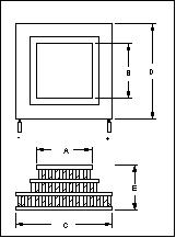
6. Off the Shelf TECs to meet Requirements
Standard Marlow and Melcor devices that best match the specified TEC requirements are outlined in Tables 2 and 3, with dimension diagrams provided in Figures 6 and 7. It should be noted that, with regard to this application there are no standard devices from these manufactures that out perform those detailed below.
Marlow
|
|
Model: |
M12064T(AB) |
M12063T(AB) |
|
|
Stage: |
2 |
3 |
|
THOT=27°C |
Tmax(Dry N2) °C: |
92 |
83 |
|
Qmax: |
9.6 |
14.0 |
|
|
Imax: |
5.6 |
5.0 |
|
|
Vmax: |
8.2 |
8.4 |
|
|
Dimensions |
Dim A (mm): |
29.6 |
29.6 |
|
Dim B (mm): |
29.6 |
29.6 |
|
|
Dim C (mm): |
13.0 |
19.6 |
|
|
Dim D (mm): |
13.0 |
19.6 |
|
|
Dim E (mm): |
7.4 |
7.4 |
|
|
|
Hot Tolerance ± mm: |
0.4 |
0.4 |
Melcor
Figure 7: Melcor TEC Dimensions
|
|
|
|
THOT=25°C |
Dimensions (mm) |
||||||
Catalogue Number |
Stage |
IMax (Amps) |
QMax (W) |
VMax (Volts) |
DTMax (°C) |
A |
B |
C |
D |
E |
|
2 CP 055 065-71-31 |
2 |
4.3 |
12.65 |
8.6 |
85 |
20 |
20 |
30 |
30 |
7.2 |
|
2.8 |
16.05 |
15.5 |
83 |
30 |
30 |
30 |
30 |
7.1 |
||
|
2 SC 040 050-127-63 |
10.3 |
30.22 |
8.6 |
85 |
30 |
30 |
44 |
44 |
8.9 |
|
|
6 |
34.51 |
15.5 |
83 |
40 |
40 |
40 |
40 |
7.5 |
||
|
2 CP 085 065-71-31 |
9.5 |
59.25 |
15.5 |
81 |
62 |
62 |
62 |
62 |
8.9 |
|
|
2 SC 055 045-127-63 |
||||||||||
|
2 SC 085 065-127-70 |
||||||||||
|
3 CP 055 065-127-71-31 |
3 |
3.5 |
12.58 |
15.4 |
96 |
20 |
20 |
40 |
40 |
10.4 |
|
8.4 |
15.6 |
7.7 |
97 |
22 |
22 |
44 |
44 |
12.9 |
||
|
3 CP 085 065-71-31-17 |
||||||||||
It can be seen that Melcor offer more TECs that meet the thermal requirements, and can provide a greater heat rejection. However, these devices are, in general, larger than the Marlow devices. It is envisaged that the CCD will be mounted directly on top of the TEC, and consequently the TEC's top lateral dimensions must be suitably small. The CCD47-20 has underside lateral dimensions of 42.0mm by 22.73mm. Therefore, the Marlow devices should have dimensions C and D less than this, and Table 2 reveals that they both do. On the other hand, the Melcor devices should have dimensions A and B less than this, and Table 3 illustrates that only models 2 CP 055 065-71-31, 3 CP 055 065-127-71-31, and 2 CP 085 065-71-31-17 demonstrate this. Therefore, there are five off-the-shelf TEC products available from these two manufacturers that meet the both the thermal and geometric specification. It should be noted that the device characteristics displayed in Tables 2 and 3 are specified for a specific hot side temperature. For Marlow this is THOT=27°C, while for Melcor it is THOT=25°C. In our case a THOT of 16°C is anticipated, therefore, the presented characteristics are not exact, nevertheless they do provide a pointer to the most suitable device.
7. Device Evaluation
The Marlow design guide was revisited to decide which of the five highlighted TEC devices is most suitable for this application. From the Marlow design guide's performance graphs, each of the device's minimum QMax and optimum QMax value were calculated. Furthermore, each TEC's current and voltage requirements for 59°C temperature difference and subsequent power consumption were estimated (note that 27W was previously assumed). The results are summarised below in Table 4:
|
Device |
1 |
2 |
3 |
4 |
5 |
|
Model |
M12064T (AB) |
M12063T (AB) |
2 CP 055 065-71-31 |
3 CP 055 065-127-71-31 |
3 CP 085 065-71-31-17 |
|
Manufacturer
|
Marlow |
Marlow |
Melcor |
Melcor |
Melcor |
|
Device DTMax (°C) |
92 |
83 |
85 |
96 |
97 |
|
Min. Required QMax (W) |
8.3 |
10.34 |
9.68 |
7.69 |
7.69 |
|
Optimum QMax (W) |
12.5 |
14.28 |
13.64 |
12.5 |
12.5 |
|
Device QMax (W) |
9.6 |
14 |
12.65 |
12.58 |
15.6 |
|
Device Efficiency w.r.t. Optimum QMax |
77% |
98% |
93% |
100.1% |
124.8% |
|
Required Current For DT=59°C (A) |
4.37 |
3.65 |
3.22 |
2.10 |
4.54 |
|
Required Voltage For DT=59°C (V) |
6.0®6.7 |
5.7®6.6 |
6.0®6.9 |
8.3®10.5 |
3.7®4.8 |
|
TEC Power Consumption (W) |
26.2®29.3 |
20.8®24.1 |
19.3®22.2 |
17.4®22.1 |
16.8®21.8 |
Table 4: Estimate of TECs Performance for Given Application Parameters
From the results presented in Table 4 it can be seen that device 2 is the preferred Marlow TEC, with a superior efficiency and lower power consumption. However, device 5 (3-stage Melcor TEC) has the best overall performance, displaying an efficiency of 124.8% with respect to optimum QMax, that is the ratio of the device's QMax to the optimum QMax. This means that device 5 could be driven harder to achieve a greater temperature difference and consequently lower CCD dark currents. In addition, its power consumption is the lowest of the presented devices, which will result in a lower THOT side than predicted in Section 4, and consequently a lower cold side for the same temperature difference. It is therefore proposed that the Melcor 3-stage TEC, model 3 CP 085 065-71-31-17, be employed as the ULTRACAM heat pump.
8. Conclusions
ULTRACAM demands low dark current rates, specifically less than 0.1e/pixel/sec. It has been show that to obtain this performance a CCD47-20 temperature of less than 233K is required. Consequently, the desired device temperature was stated as 230K, which would yield a dark current of 0.05e/pixel/sec. A TEC heat pump will be used to achieve this temperature, and in Section 3 it was revealed that the thermal load on such a device would be less than 3W. Moreover, Section 4 demonstrated that with the heat exchanger being used a temperature difference of 59°C would be required.
It was shown using Marlow Industries' design guide that in general a 2-stage TEC with a QMax above 10W and optimally 13.6W, or a 3-stagee TEC with a QMax above 7.89W and optimally 10W is required. In addition, the device's top-side lateral dimensions should be less than 22.7mm x 42.0mm so that it can be mounted directly to the underside of the CCD47-20. Marlow provide two off-the-shelf products that meet these specifications: M12064T(AB), and M12063T(AB), while Melcor provide three: 2 CP 055 065-71-31, 3 CP 055 065-127-71-31, and 3 CP 085 065-71-31-17. It was shown from subsequent analysis that the M12063T(AB) is the preferred Marlow device, however the Melcor 3 CP 085 065-71-31-17 provided the best theoretical performance, and is consequently proposed for this application. The only point of concern is that this device only just meets the geometric specification (top side lateral dimensions 22mm x 22mm), which may deem it unsuitable! The second choice device would be the Melcor 3 CP 055 065-127-71-31, or the Marlow M12063T(AB).
9. Feedback from manufactures
Marlow and Melcor have been contacted for cost quotes, and assistance on the best choice of TEC. Marlow responded quickly and have agreed that the M12063T(AB) is their most suitable product for our application. The cost is £176.00 per device.
Melcor have still to respond.
1 ULTRACAM Webpage: http://www.shef.ac.uk/uni/academic/N-Q/phys/people/vdhillon/ultracam/index.html
2 CCD47-20 Data Sheet, https://www.teledyneimaging.com/en/aerospace-and-defense/products/sensors-overview/ccd/ccd47-20/
3 Marlow Industries, Inc. 'Thermoelectric Cooling Systems Design Guide', http://www.marlow.com
4 D.J. Burt 'CCD Performance Limitations: Theory and Practice', CCD Technical Note 18, EEV Limited, Waterhouse Lane, Chelmsford, Essex, England.
5 NESLAB, http://www.neslabinc.com
6 Frank P. Incropera, and David P. DeWitt, Introduction to Heat Transfer 3rd Edition, John Wiley & Sons, New York, 1996.