The Ultracam camera control and data acquisition system
Steven
Bearda, Andrew Vicka, David Atkinsona,
Vik Dhillonb, Tom Marshc, Stewart
McLaya,
Mark Stevensonb and Chris Tierneya
a UK Astronomy Technology Centre, Blackford Hill, Edinburgh, EH9 3HJ, UK
b Department of Physics and Astronomy, University of Sheffield, Sheffield, S3 7RH, UK
c Department of Physics and Astronomy, University of Southampton, Southampton, SO17 1BJ, UK
ABSTRACT
Ultracam is a high speed, three channel CCD camera designed to provide imaging photometry at high temporal resolution, allowing the study of rapidly changing astronomical phenomena such as eclipses, rapidly flickering light curves and occultation events. It is designed to provide frame rates up to 500 Hz with minimum inter-frame dead time and to time-tag each frame to within 1 millisecond of UT. The high data rates that this instrument produces, together with its use as a visitor instrument at a number of observatories, have lead to a highly modular design. Each major service (camera, control, sequencing, data handlers, etc.) is a separate process that communicates using XML documents via HTTP transport, allowing the services to be redeployed or reconfigured with minimal effort. The use of XML and HTTP also allows a web browser to act as a front end for any of the services, as well as providing easy access to services from other control systems. The overall design allows for simple re-engineering for a variety of imaging systems, and is already expected to provide control of IR arrays for the UKIRT Wide-Field Camera project. The instrument has been successfully commissioned on the William Herschel Telescope.
Keywords: Instrumentation, Ultracam, Time resolution, Imaging, Photometry
INTRODUCTION
Ultracam is designed for the observation of rapidly changing astronomical phenomena[1]. It is designed to image a target simultaneously in three different colours at rates of up to 500 Hz and to time stamp those images to within 1 millisecond (ms) of Universal Time (UT). Ultracam is a travelling instrument which can be deployed at many of the world’s major telescopes. It has recently been commissioned on the William Herschel Telescope on La Palma and is planned to be shared with Aristarchos and the ESO Very Large Telescope (VLT).
The camera can read out a full frame of 1024 x 1024 pixels in around 2 seconds, but the frame rate of the camera can be increased for a variety of different science projects by narrowing down the readout to small windows (up to six windows are allowed on each camera) or by binning. By changing the frame rate, the camera can be used for a variety of science projects as follows.
On timescales of milliseconds it can be used to study the optical emission from pulsars and to search for the optical analogue of the kilohertz quasi-periodic oscillations and related small-scale accretion phenomena found in X-ray binary stars.
On timescales of a hundredth of a second it allows non-redundant-mask imaging of nearby giant stars[5].
On timescales of a tenth of a second it can be used to construct echo maps, enabling the geometries of cataclysmic variable stars and X-ray binary stars to be determined, and a search for quasi-periodic oscillations and dwarf-nova oscillations in cataclysmic variables to be carried out[2].
On timescales of a second it can be used to measure the sharp ingress and egress of the eclipse of white dwarfs in close binary stars, thereby determining their masses and radii for comparison with theory, and constructing eclipse maps of the accretion discs in cataclysmic variables.
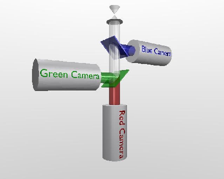
Figure 1 The light path through Ultracam
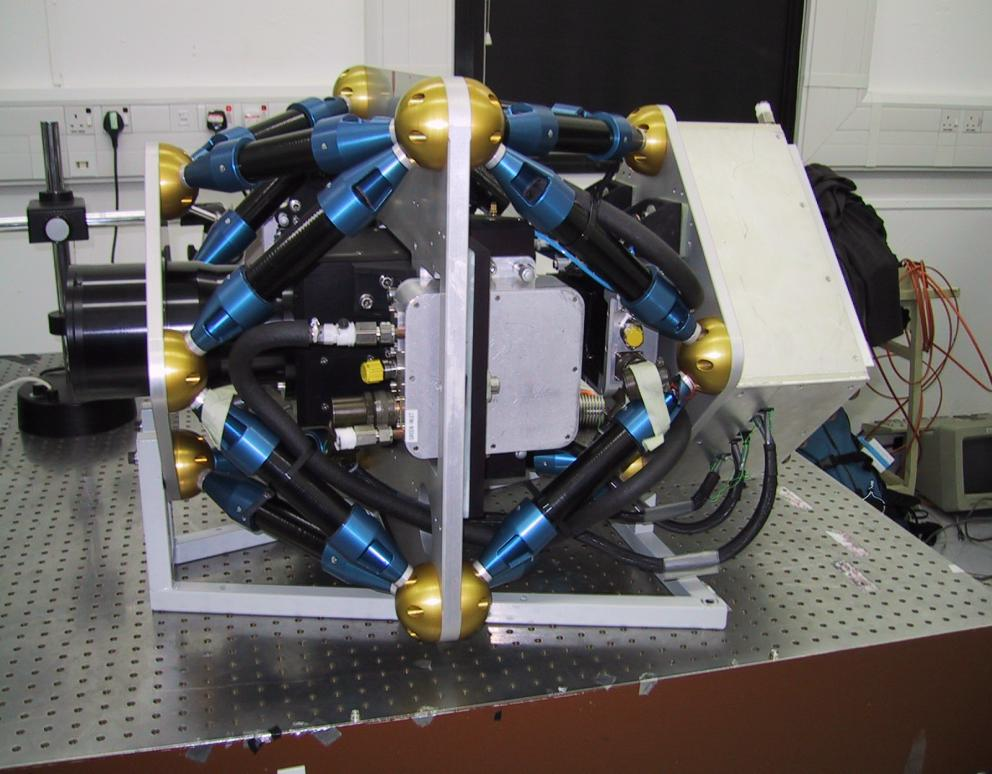
Figure 2 Ultracam on the test bench
To achieve these scientific goals the instrument has low-noise, high quantum-efficiency detectors, and can make a rapid series of short exposures with minimal dead-time between those exposures. It provides images in three wavelength bands so that a stellar spectrum may be distinguished from a black-body (which cannot be done with two or fewer bands) and the images in those three bands are recorded simultaneously, which overcomes the serious problems suffered by filter wheel based cameras when the object varies between the exposures in different filters. Unlike a single-channel photometer, Ultracam provides two-dimensional information, which allows comparison stars and sky to be measured simultaneously with any object, increasing the photometric accuracy and allowing measurements to be taken in non-photometric conditions.
The Ultracam project is a collaborative venture between the scientists and engineers of the University of Sheffield (who designed and built the mechanical components, procured the optics and integrated the components into the instrument), the University of Southampton (who designed and implemented the data reduction facilities) and the UK Astronomy Technology Centre (who designed the optics and designed and built the cameras and camera controller). It is the camera control components on which this paper will concentrate.
INSTRUMENT OVERVIEW
2.1 Camera hardware
The light path through Ultracam is shown in Figure 1 (Figure 1 The light path through Ultracamabove) and the instrument itself can be seen on a test bench in Figure 2. The incoming light is separated into three wavelength components and directed to the three separate cameras using two dichroics, as shown in Figure 1. The cameras and optics are held firmly in place by an octopod of supporting struts (Figure 2), and the camera has a modular optical system that can be re-optimised for use at different focal-lengths and allow it to be redeployed on a variety of different telescopes. In Figure 2 the light enters the instrument from the left hand side. On the right hand side is a water-cooled box, which contains the camera control electronics and connects to the main control computer through fibre-optic cables.
Figure 3 The Ultracam Hardware Layout
The camera hardware (shown schematically in Figure 3 Figure 3 The Ultracam Hardware Layoutabove) is based around an SDSU controller built by San Diego State University. The only connections this hardware requires with the outside world are a 240V AC power supply and a 100 Base T Local Area Network (LAN) connection. The SDSU controller is hosted from a rack-mounted PC running Linux patched with real-time (RTlinux) extensions. Accurate time stamps are obtained with the aid of a GPS receiver connected to a serial port. The PC communicates with the SDSU hardware through a San Diego PCI (Peripheral Component Interconnect) interface card and two 50 MHz optical fibres. Besides communicating through the fibres, the SDSU controller has the ability to interrupt the PC using its parallel port interrupt line. The SDSU controller and PCI card both have on-board digital signal processors (DSPs) which can be programmed by downloading assembler code from the host PC.
2.2 Readout speed
Ultracam can be programmed to repeat an exposure any number of times in quick succession or to repeat exposures continuously until commanded to stop. The current Ultracam system uses 1024 x 1024 pixel frame transfer CCDs, with 13 μm pixels, and supports a variety of different readout modes, as illustrated in Figure 4.
Figure 4 Ultracam CCD readout options
The lower sections of the frames in Figure 4 represent the masked-off frame transfer area. The CCDs have two readout channels which can, in parallel, read out pixels from the left and right sides of the chip as separated by the dotted lines in the diagrams. The readout options are:
Full frame mode. This mode provides a slower readout but gives a wider field of view (e.g. 5 arcminutes at 0.3 arcseconds per pixel on the WHT). It can be used for calibration frames and for applications requiring a wide field of view and slower speed. At maximum readout speed a full frame can be read out in about 2 seconds. Ultracam also supports a more accurately calibrated full frame mode in which additional overscan pixels outside the exposed area of the chip are read out. A faster readout time (of about 1.3 seconds) with reduced dead time can be achieved using a full frame mode in which the CCD is not reset between exposures.
Windowed readout. Ultracam achieves high speeds in windowed readout mode. Frame rates of up to 100 Hz can be achieved. Only the pixels from up to three variable-sized pairs of windows are read out. The windows can be positioned anywhere on the chip subject to the constraint that they cannot overlap in the Y direction and each of the 1, 2 or 3 windows in the left hand half of the chip must have a counterpart on the right hand side of the same size and at the same Y position.
Drift scan mode. In this mode Ultracam achieves its fastest speed by repeatedly making an exposure and rapidly shifting the charge into the frame storage area. The resultant stack of windows is continuously shifted down the frame storage area and read out at the bottom, while at the same time new frames are exposed and added at the top. This mode significantly reduces any dead time between exposures, allowing frame rates up to 500 Hz to be realised.
In all three of these modes it is possible to reduce the data rate, at the expense of lower resolution, by binning the pixels before transmitting them back to the host. Further adjustments to the readout speed, at the expense of readout noise, can be made by selecting different clocking parameters. As an example, Table 1 shows the frame rates that could be achieved in drift scan mode using a 24 x 24 pixel window situated at the edge of the storage area. The sampling time represents the time the camera spends reading one pixel. The vertical clock time (V-clock) is the time spent shifting a row of pixels without reading them and the horizontal clock (H-clock) is the time spent shifting a single pixel within a row without reading it. The dead time is the time when the chip is not integrating, which for a 24 x 24 pixel window in drift scan mode is the time taken to shift 24 rows into the frame transfer area: 24 x 24 μs = 0.576 ms. By comparison, in windowed readout mode the dead time is the time taken to do a complete frame transfer of 1033 pixels: 1033 x 24 μs = 24.8 ms At the moment only the 1.44 μs and 0.5 μs H-clock times have been used for observations. The 0.2 μs mode requires further optimisation to reduce noise effects. There is also the possibility of reducing the V-clock times down to 5 μs, but this currently produces peppered noise on the images and is less important than reducing the H-clock noise in drift-scan mode.
|
Binning |
Sampling time (CDS) |
Vertical clock time (V-clock) |
Horizontal clock time (H-clock) |
Dead time |
Frame rate |
|---|---|---|---|---|---|
|
1x1 |
2 μs/pixel |
24 μs |
1.44 μs |
0.576 ms |
48 Hz |
|
1x1 |
2 μs/pixel |
24 μs |
0.5 μs |
0.576 ms |
114 Hz |
|
1x1 |
2 μs/pixel |
24 μs |
0.2 μs |
0.576 ms |
205 Hz |
|
4x4 |
2 μs/pixel |
24 μs |
0.2 μs |
0.576 ms |
535 Hz |
Table 1 Dead times and frame rates for Ultracam in drift scan mode as a function of binning factors and clock times.
2.3 CCD characteristics
The measured detective quantum efficiency (DQE) of the blue and green Marconi CCD chips used in Ultracam is above 95% in the centre of their bands and the red chip is just below 90% in the centre of its band. The readout noise on the three chips, as measured by Marconi, is detailed in Table 2. Our own measurements at two different sampling speeds (for the left channel only) are included on the table in brackets for comparison.
|
|
Sampling time (CDS) |
RED (midband) |
GREEN (broadband) |
BLUE (broadband) |
|---|---|---|---|---|
|
Left channel: |
10 μs/pixel |
4.2 e- (3.3 e-) |
3.6 e- (3.2 e-) |
3.7 e- (3.2 e-) |
|
2 μs/pixel |
(4.7 e-) |
(5.0 e-) |
(5.4 e-) |
|
|
Right channel: |
10 μs/pixel |
4.3 e- |
3.5 e- |
3.5 e- |
|
|
Table 2 Noise figures for the three Ultracam CCDs, courtesy of Marconi, compared with our measurements
SOFTWARE DESIGN PHILOSOPHY
3.1 Keep it simple
Because Ultracam is to be reusable and shareable between many observatories, the main design philosophy has been to keep the camera controller as simple as possible[4]. We have deviated from the approach used in most other SDSU systems, in which the controller has one large multi-purpose application downloaded, and have instead opted for the following philosophy.
The SDSU controller is loaded with DSP code that contains only one executable application for one particular purpose. We have several very simple SDSU applications rather than one complex one. The applications can still be configured using parameters written to the DSP’s memory. Typical Ultracam applications are “power on”, “power off”, “make full frame exposures”, “make windowed exposures”, “make drift scan exposures”. The number of exposures, readout speed, exposure time and binning are configurable, as are the positions and sizes of the windows in the windowed modes, but there are separate applications for full frame readout with overscan and full frame readout without clearing the CCD and separate applications for reading out 1, 2 or 3 pairs of windows.
When a new function is needed on the SDSU controller, a new application is downloaded.
The SDSU controller DSP always has the same five commands, which are “reset”, “read memory”, “write memory”, “execute current application” and “stop executing application”. The PCI interface DSP also recognises these same five commands and two additional ones “send packet to controller” and “send packet to host” (which are used to forward data packets through the PCI interface):
All the real work is done on the SDSU controller DSP: the DSP on the PCI interface card merely forwards commands and data between the host and SDSU controller. The PCI interface is designed to be able to receive and forward a command or a data packet at any time.
The advantage of our approach is that it simplifies the DSP software, making that code easier to develop and debug. Keeping the DSP software simple also lessens the chances of running out of DSP memory, which can make programming the SDSU difficult. It also simplifies the host software, which only needs to know about the same five commands no matter what has been downloaded to the DSP. Keeping the PCI card dumb simplifies the communication between the host and the SDSU controller and lessens the chances of that communication hanging up because one of the processors isn’t in the right state.
Our approach has its disadvantages. Each time a new controller function is needed a new application has to be downloaded. This takes much less than a second, so the approach is well suited to a camera like Ultracam where the camera spends a significant amount of time carrying out one function (e.g. windowed exposures) over and over again. Applications, such as wavefront correction, in which the camera mode needs to be switched in milliseconds rather than tenths of a second may not suit this approach, although there is no reason (other than introducing complexity) why a single large Ultracam application could not be configured to run different code according to the value of a parameter.
3.2 Use of standard communication protocols
As well as simplifying the low level software, we decided to make the Ultracam system highly transportable by using international standard communication methods. All messages are transmitted within the Ultracam system using XML documents transmitted using the HTTP protocol. SDSU applications are also described using XML documents, which allows the applications to be self-describing.
Figure 5 (Figure 5 The Architecture of the Ultracam softwarebelow) shows the architecture of the Ultracam software. The process begins with an engineer creating the SDSU applications with a text editor and DSP cross compiler. Normally when developing an SDSU application, the cross compiler converts the assembler source code into a “common object file format” (COFF) file – an ASCII file containing the various numbers and symbols to be downloaded to the DSP memory. In the Ultracam system each DSP application is described using an XML document which contains the following information.
A reference to the COFF object code. This code is downloaded to the controller when the application is processed.
The names, addresses, memory spaces and accessibility of all the application parameters. This information is used by the camera controller so it knows where each parameter is located. It is also used by the Ultracam user interface to prompt the user for all the user-accessible application parameter values.
Expressions involving application parameters which must be evaluated and tested before or after executing the application. These may be used to ensure that each application parameter has a sensible value before executing the application, or that the application has produced a sensible result after being executed. Because these expressions are strings contained in the XML document, they do not need to be programmed into the Ultracam software itself. New applications can be provided with new sets of condition checks without needing to reprogramme the camera controller.
Figure 5 The Architecture of the Ultracam software
A description of the data generated by the application, including the size and shape of the data, the size, shape and number of windows, the number of channels read out and the ordering in which the data from various channels appears in the data. The data description can include expressions involving application parameters. Although Ultracam currently controls two channel devices, the existing high level software may be configured to control other kinds of devices by supplying new DSP code together with an appropriate XML document.
The Ultracam Sequencer provides the user interface for the camera. It presents the user with a choice of applications found in the XML repository. When the user selects an application and defines the parameters associated with it, that selection is transmitted to the camera control software as a “configuration” XML document which contains a reference to the “application” XML document together with a list of parameter names and required values. The contents of this XML document are decoded and the application code transmitted to the SDSU control software. The application parameters can be updated and the application executed at any time by command from the sequencer.
One or more data handling servers can be running in parallel. The camera control software communicates with these through the shared data buffer. The data handlers are synchronised with the camera control software using semaphores. Each data handler reads static camera configuration information from the XML repository and dynamic configuration information from the shared data buffer, and uses these two sets of information to generate the data.
Figure 6 The Ultracam real-time interfaces
REAL-TIME INTERFACES
4.1 Message passing
The real-time interfaces within Ultracam are shown schematically in Figure 6. The Camera Control Software and Data Handling Software run in user space and communicate with the Camera Interface and Buffer Handler real-time tasks through FIFO buffers, which absorb any latency in the non-real-time software and allow the real-time code to run at full speed. The camera interface forwards commands and responses to and from the SDSU PCI card and the Buffer Handler manages a shared memory buffer. When the SDSU PCI card interrupts to say it has data available, the Buffer Handler doesn’t handle the raw data but merely passes the address of the next available buffer to the PCI card, which can then write raw data directly to the PC memory by Direct Memory Access (DMA). Figure 7 is a state chart showing how messages to and from the PCI card are managed.
4.2 Time stamping
One of the crucial requirements on the Ultracam system is that exposures are time stamped to within 1 ms. Ultracam uses a stand alone GPS aerial to provide these high accuracy time stamps. Every ten seconds, a time stamp is requested from the GPS aerial by the “GPS THREAD” task (Figure 6) using a low latency signal. The time taken for the signal to get to the GPS can be estimated from the length of the GPS cable and the timing characteristics of the port used. The GPS responds by sending a data packet containing the UT (and various measures of quality) corresponding to the time that it received the signal. By reading the internal PC clock at the time that the UT is requested, the offset between the internal clock and UT is recalculated every 10 seconds. The computer motherboard was specially selected to provide a system clock that does not vary by more than 10 μs over a 10 second period, note that this is not true of most single processor PC motherboard clocks. Although the GPS receiver provides UT, strictly it provides a “GPS time” converted to UT and handles leap seconds in a predictable manner.
Whenever an exposure is started the SDSU controller sends a synchronisation interrupt, which triggers the execution of the “TIMESTAMP IRQ” (Figure 6). This task then writes the current system time (which has been kept up to date by the “GPS THREAD”) into a real-time FIFO. The data handling software reads the time stamp from the FIFO and writes it to the header of the next buffer of raw data written to the shared memory. The time stamps and raw data remain synchronised because the number of time stamps written by the “TIMESTAMP IRQ” is always the same as the number of buffer addresses written by the "BUFFER HANDLER”. The software reports an error if these counts ever differ.
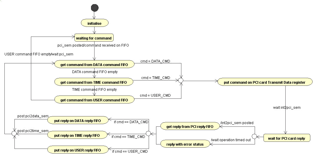
Figure 7 State diagram showing the Ultracam PCI command interface
5. INSTRUMENT STATUS
5.1 The first commissioning
Ultracam was commissioned for the first time on the William Herschel Telescope (WHT) in La Palma in May 2002, with reduced functionality. The system was limited to large windows (and hence low frame rates, about 10 Hz maximum). The instrument was also commissioned using temporary mounts which did not allow for fine adjustment of the alignment between the three cameras, although it was still possible to achieve an alignment of less than 4 pixels of linear shift with insignificant rotation or magnification. Nevertheless, even with this reduced functionality the instrument achieved some exciting new science, including some simultaneous observations with the XMM-Newton and RXTE X-ray satellites[3].
The fact that the instrument is designed to be used stand-alone worked in our favour. There were no observatory interfaces to check out and all the necessary lab tests had already been carried out before the instrument was shipped. This meant that within half a night of commissioning the instrument was ready to begin science observing and, with only a few minor hiccups, continued to work successfully for the remainder of the five nights. Figure 8 shows a first light image of M51, a 3 second exposure.
Figure 8 First light — M51 imaged with Ultracam (full chip image)
Figure 9 Light curve of the eclipsing binary NN Ser. (relative flux vs. time)
Figure 9 and Figure 10 show the kind of time-resolved science Ultracam is designed for (at least at the low frame rates available during the first commissioning). Figure 9 shows the light curve of the eclipsing binary system NN Ser. (15 52 56 +12 54.7 J2000). Each point on the graph represents a 2.0 second exposure. The upper curve in Figure 9 is the normalised flux detected in the red arm, the lower is the normalised flux detected in the green arm. The blue arm has not been plotted, since the comparison star chosen is weak in blue. The rise in the centre of the curve is due to a reflection effect, where the irradiated inner hemisphere of the cooler star comes into view.
Figure 10 The deep eclipse of NN Ser. (relative flux vs. time)
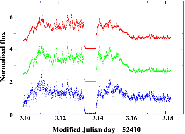
Figure 11 The light curve of HU Aqr. in red (upper), green
(middle) and blue (lower) channels.
The green and red plots have
been shifted upwards respectively by 2 and 4 units of flux.
Figure 10 is an expanded plot of the eclipse ingress of Figure 9. The eclipse period, during which the hotter star is partially obscured, is visible as a slope lasting about 60 seconds. The relative widths of the slope and the duration of the eclipse minimum can be used to estimate the size of the two stars, although a full light curve fit is more accurate, and the various edges of the light curve need to be resolved to properly constrain the fit.
Figure 11 shows the light curve of the polar Hu Aqr., which was also observed during the first commissioning. Hu Aqr. consists of a white dwarf accreting material onto its magnetic poles from a red dwarf companion star. The light curve shows intense flickering from the accreting poles and the eclipse of the poles by the companion star (showing the 2-3 second transition into eclipse). The plot shows how Ultracam is able to resolve the rapid flickering in the red, green and blue bands simultaneously. The eclipse of the entire disc of the white dwarf takes over 30 seconds, but isn’t noticeable since most of the light comes from the accretion region.
5.2 Current status
At the time of writing, Ultracam is back in the lab. being prepared for its second commissioning on the WHT in September 2002 when we hope to achieve its full readout speed. Further proposals are in the pipeline, including a proposal to use Ultracam as an interferometric detector, using non-redundant mask techniques with an adaptive optics system. After the second commissioning Ultracam becomes available for shared use with other telescopes, including the 8m-class ESO VLT.
6. SUMMARY AND DISCUSSION
The Ultracam camera is capable of delivering images at a fast frame rate (up to 500 Hz) in three simultaneous wavelength bands, while time stamping each frame to with 1 ms of UT. The instrument itself is portable and becomes available for sharing with other telescopes in late 2002. The instrument commissioned easily because there were no interfaces to observatory systems to be tested, and most of the commissioning time was devoted to science. The instrument allows the observation of rapidly changing astronomical phenomena.
The camera controller is designed to be fast, simple and reusable, and uses international standard communication protocols. At the time of writing it has not yet achieved its full readout speed potential, but we are hoping to achieve this at the second Ultracam commissioning in September 2002. The controller will be reused to control the detectors for the UKIRT Wide Field Camera and may find applications in other projects requiring a simple but fast and reliable CCD controller.
ACKNOWLEDGEMENTS
This work was funded by the Particle Physics and Astronomy Research Council. We are grateful to Vik Dhillon and Tom Marsh for allowing an early preview of the science results to be shown in this paper.
REFERENCES
V. Dhillon and T. Marsh, 2001. “ULTRACAM – studying astrophysics on the fastest timescales”, New Astronomy Reviews, 45, Issue 1-2, 91-95.
V. Dhillon, T. Marsh, J. Kelly, R. Pashley, M. Stevenson, D. Atkinson, S. Beard, D. Ives, T. Peacocke, C. Tierney and A. Vick, 2002. “Ultracam – a fast triple-beam CCD camera”, The Physics of Cataclysmic Variables and Related Objects, ASP Conference Proceedings, Vol. 261, ISBN: 1-58381-101-X., Astron. Soc. Pac, San Francisco.
V. Dhillon et al., 2002, MNRAS, in preparation.
C. Tierney and S. Beard, 2002. “The Design of an Object-Oriented, Distributable Camera Control System for the Ultracam Project”, in Astronomy Data Analysis and Software Systems XI, Astron. Soc. Pac, San Francisco.
R. Wilson, V. Dhillon and C. Haniff, 1997. “The changing face of Betelgeuse”, MNRAS, 291, 819.
For further information go to the Ultracam home page on http://www.shef.ac.uk/~phys/people/vdhillon/ultracam/.