| focal reducers and extenders |
|
One problem with the simplest form of imager we have just seen is that the plate scale, i.e. the number of arcseconds per pixel on the detector, may be unsuitable for the size of the detector and its pixels, or vice versa. For example, a telescope with a focal length of 10 m will have a plate scale of approximately 20 "/mm. If used with a CCD of 1000 x 1000 pixels, each of 10 microns, the field of view would be only 3.3' x 3.3', and each pixel would correspond to only 0.2". If wide field imaging is required, such a setup would be of limited use. Moreover, if the seeing at the site is typically 2", the seeing disc would have a FWHM of 10 pixels, which is very oversampled (more on this later). Replacing the telescope for one of a shorter focal length, or the detector for one with more and/or larger pixels, is usually neither a practical nor economical solution, so what can be done?
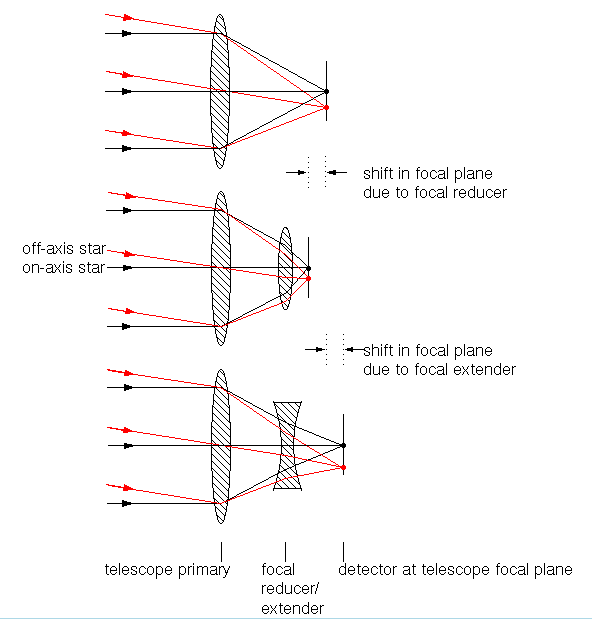
One possibility is to use a focal reducer. This is a positive lens (or combination of lenses) which is usually placed in front of the focal plane, in the converging beam from the telescope, as shown in figure 71. The lens acts to shorten the focal length of the telescope, resulting in a larger plate scale and hence a larger field of view. Figure 71 also shows the opposite of a focal reducer - the focal extender or Barlow lens - which has negative optical power and acts to lengthen the focal length of the telescope, and hence decrease the plate scale and field of view.
Note that the focal length of a simple imager (such as shown in the top-left panel of figure 71) is simply the focal length of the telescope, but the focal length of a multi-element astronomical imager (like that shown in the centre- and bottom-left panels of figure 71) is a more complicated function of the focal lengths of the individual elements. In the limiting case of inserting a filter, which has no optical power (i.e. infinite focal length), the focal length remains unaltered, although the distance between the last lens and the focal plane changes (as shown in figure 70).
| figure 71: |
Left-top: the light path of a simple imager. Left-middle: the light
path of an imager with a focal reducer. Left-bottom: the light path of
an imager with a focal extender. Note the shift in the position of the
focal plane when using a focal reducer/extender, which can be
compensated for by refocusing the telecope. This shift should not be
confused with the change in the focal length induced by the focal
reducer/extender. Right top: photograph
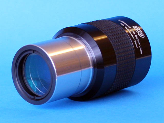
of a 0.63x focal reducer. Right bottom: photograph
of a 2.5x focal extender (or Barlow lens).
|
 |
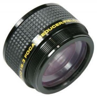  |
The top-right panel of figure 71 also shows
a photograph of the 0.63x focal reducer used in the imager on
Sheffield's f/10 robotic telescope, ROSA, which reduces
the focal length of the telescope by a factor of approximately 0.63,
i.e. the focal ratio changes from f/10 to f/6.3.
(The precise amount of reduction depends on the characteristics of the
telescope and the positioning of the focal reducer). Since the plate
scale is inversely proportional to the focal length, this means that
the plate scale (and hence the field of view) is increased by a factor
of 1.6. Similarly, the bottom-right panel of figure 71 shows a photograph of a 2.5x
Barlow lens, which decreases the field of view by this factor.