An astronomical spectrograph splits, or disperses, the
light from a source into its component wavelengths. Some means of
dispersing the light is therefore required. This function used to be
performed by a prism, which exploits the fact that light of different
wavelengths are refracted by different amounts, with blue
light being refracted more than red light, as shown
in figure 86. Prism spectrographs are only
rarely found in astronomical spectrographs nowadays. There are a
number of reasons for this, including: the dispersion is non-linear,
with light in the blue part of the spectrum being dispersed more than
the red, making it more difficult to analyse; the dispersion is not
very high, and the only way of significantly increasing it is to use
two or more prisms in tandem, which starts to become inefficient due
to the loss of light at each air-glass surface and absorption within
the glass itself.
|
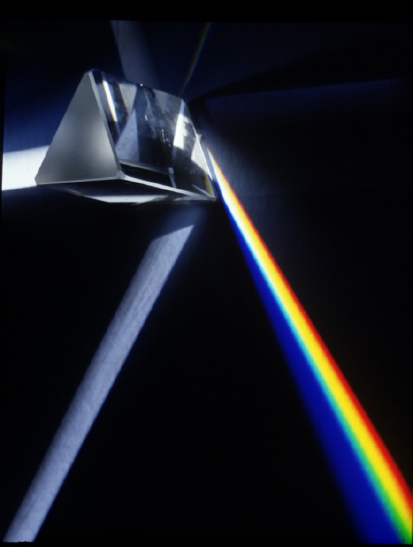
figure 86:
|
A photograph
showing how white light entering a prism from the left is dispersed into
a spectrum on exiting at the right. Note how the blue light is refracted by the
greatest angle and also dispersed the most.
|
The almost universal choice for the dispersing element in modern
astronomical spectrographs is the diffraction grating. A
diffraction grating consists of a large number of fine, equidistant,
parallel lines ruled onto a transparent glass plate so that light can
pass between the lines, but not through them. Strictly speaking, this
would be a transmission grating; a reflection
grating would have the lines ruled onto a reflective glass plate
so that only the light falling between the lines is reflected. An example of
each is shown in figure 87. Gratings with
up to 2400 lines per mm are available, produced either with a diamond
tool or photolithographic (holographic) etching.
|
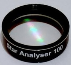
figure 87:
|
Left: photograph
of a transmission grating for the amateur astronomy market with 100
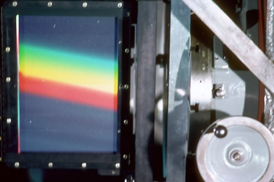
grooves per mm. Centre: photograph
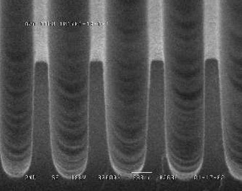
of a reflection grating mounted in a professional spectrograph. Right: a
microscopic view
of the grooves in a typical diffraction grating.
|
Light incident upon a grating will be diffracted by the lines,
producing a series of secondary wavelets emanating from the gaps
between the lines, as shown in the left-hand panel of figure 88. As each diffracted wavefront emerges
from a gap, it reinforces wavefronts from each of the other gaps,
i.e. there is constructive interference, but only at certain
angles. For example, in the left-hand panel of figure 88, the monochromatic wavefront
emerging at P reinforces the wavefront emitted from Q one cycle
earlier, which reinforces the wavefront emitted from R one cycle
earlier, etc. The effect is to form a new wavefront PYZ which travels
in a certain direction and contributes to the first-order diffracted
beam. A similar diagram could be drawn for a second-order diffracted
beam, but in this case the wave emerging at P reinforces the wavefront
emitted from Q two cycles earlier, etc. The end result is
shown in the centre-left panel of figure 88, which
shows that multiple orders emerge from a diffraction grating.
|
figure 88:
|
Schematic
showing how parallel, monochromatic wavefronts are diffracted by the
gaps in the grating, forming secondary wavefronts which constructively
interfere (left), transmitting light in certain directions only
(centre-left). Constructive interference only occurs when the path
difference between the wavefronts is equal to a whole number of
wavelengths (centre right - for incident waves perpendicular to the
grating; right - for arbitrary angle of incidence).
|
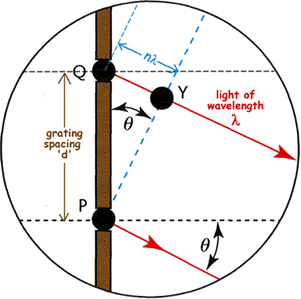
The condition for constructive interference can be derived by
inspecting the centre-right panel of figure
88. The wavefront emerging from slit P reinforces a wavefront
emitted n cycles earlier by the adjacent slit Q. This earlier
wavefront therefore must have travelled a distance of n
wavelengths from the slit. Therefore the perpendicular distance QY
from the slit to the wavefront is equal to nλ, where
λ is the wavelength of the light. Since the angle of
diffraction of the beam,  , is equal to
the angle between the wavefront and the plane of the slits, it follows
that sin = QY/QP, where QP is the
grating spacing (i.e. the centre-to-centre distance d between
adjacent slits). Substituting d for QP and nλ for
QY and rearranging gives the grating equation:
, is equal to
the angle between the wavefront and the plane of the slits, it follows
that sin = QY/QP, where QP is the
grating spacing (i.e. the centre-to-centre distance d between
adjacent slits). Substituting d for QP and nλ for
QY and rearranging gives the grating equation:
n λ = d sin .
In deriving the above form of the grating equation, we assumed an
incident beam perpendicular to the grating. If, instead, the incident
beam makes an angle
 with respect to the grating,
then the right-hand panel of figure 88 shows
that the total path difference becomes x + y =
nλ. Given this, we arrive at the more generalized form of
the grating equation:
with respect to the grating,
then the right-hand panel of figure 88 shows
that the total path difference becomes x + y =
nλ. Given this, we arrive at the more generalized form of
the grating equation:
n λ = d (sin
+ sin ).
The discussion above has considered only a monochromatic incident
wavefront. If more than one wavelength is present, each wavelength
will be diffracted through different sets of angles as defined by the
grating equation. The diffraction grating will thus disperse the light
incident upon it into its component wavelengths, as shown in figure 89. It can be seen that the zeroth order
is undispersed, which follows from the grating equation - when
n = 0, then = 0 and hence
light of all wavelengths is undeviated. The first orders (n =
±1) fall either side of the zeroth order, with the blue light
deviated the least and red the most, opposite to that observed with a
prism (figure 86). This follows from the
grating equation - for a fixed n and d, must increase as λ
increases. Outside the first order can be seen the second (n =
±2) and third (n = ±3) orders, which appear successively
wider and fainter. As we shall see, the higher dispersion in higher
orders is exploited in high-resolution spectrographs, in
conjunction with blazed gratings to
overcome the efficiency loss.
|
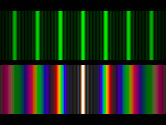
figure 89:
|
Photograph showing the diffraction pattern produced
by a monochromatic light source (top) and a white light source (bottom)
incident on a diffraction grating.
The central bright line is the zeroth order, with orders ±1, ±2 and ±3
shown either side of this. The fainter lines between the bright lines are due to the diffraction
pattern produced by the finite width of the grooves in the grating.
|
©Vik Dhillon, 12th December 2013