Paul Kerry's user guide to the ULTRACAM/ULTRASPEC computers. This
can be found
in /home/observer/userguide/ultracam_user_guide.pdf
on the data reduction PC (drpc) and a paper copy resides in the red
ULTRASPEC folder in the control room. I don't provide a link to it
here as it contains all of the system passwords.
Pumping down
This procedure is only to be undertaken by
members of the ULTRASPEC team or NARIT staff who have been trained
by the ULTRASPEC team.
- Move the rotator until ULTRASPEC is horizontal and press the
emergency stop button.
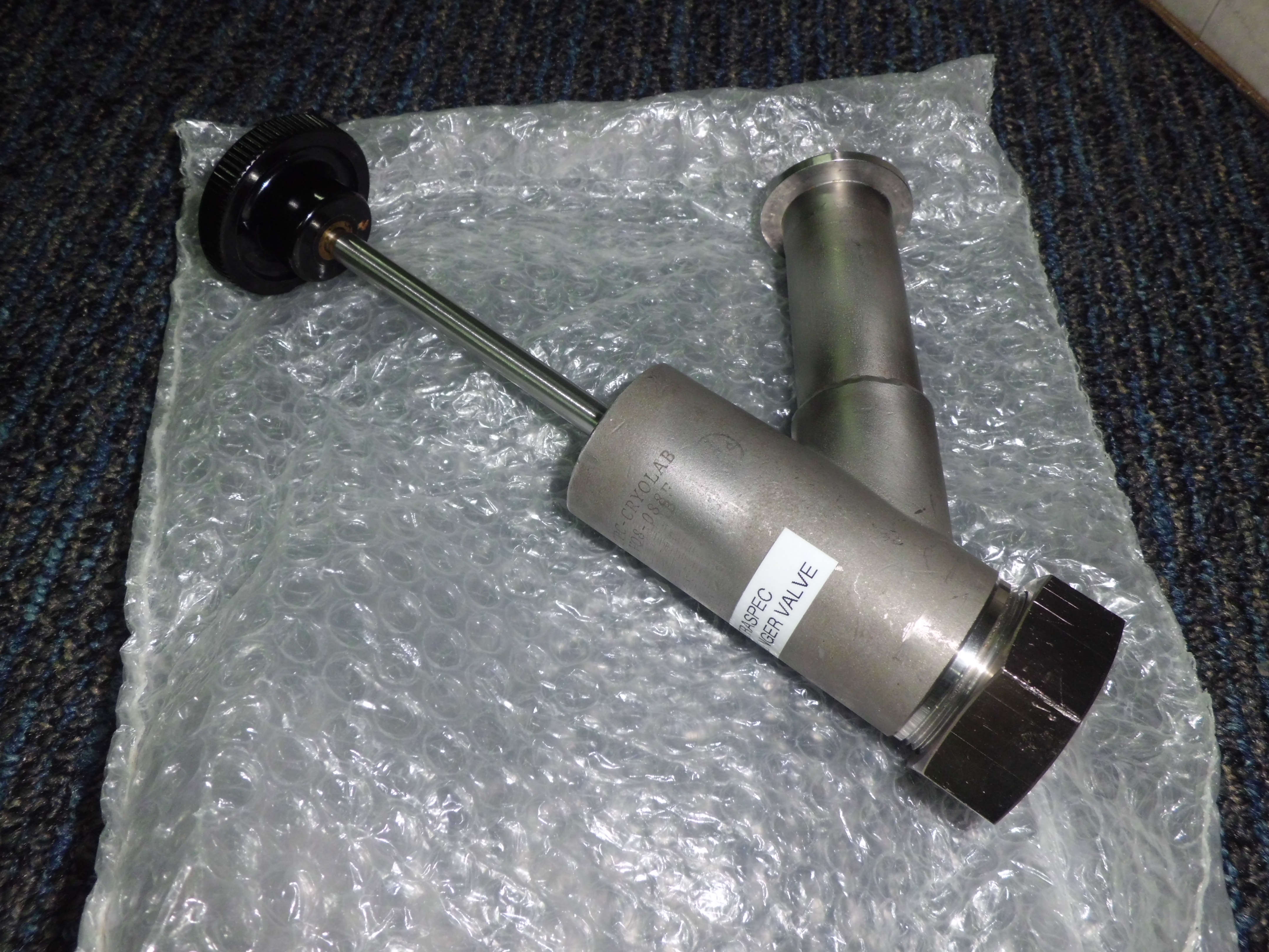
- Locate the ULTRASPEC plunger valve, which is in
the vacuum parts box in the ULTRASPEC cupboard in the dome.
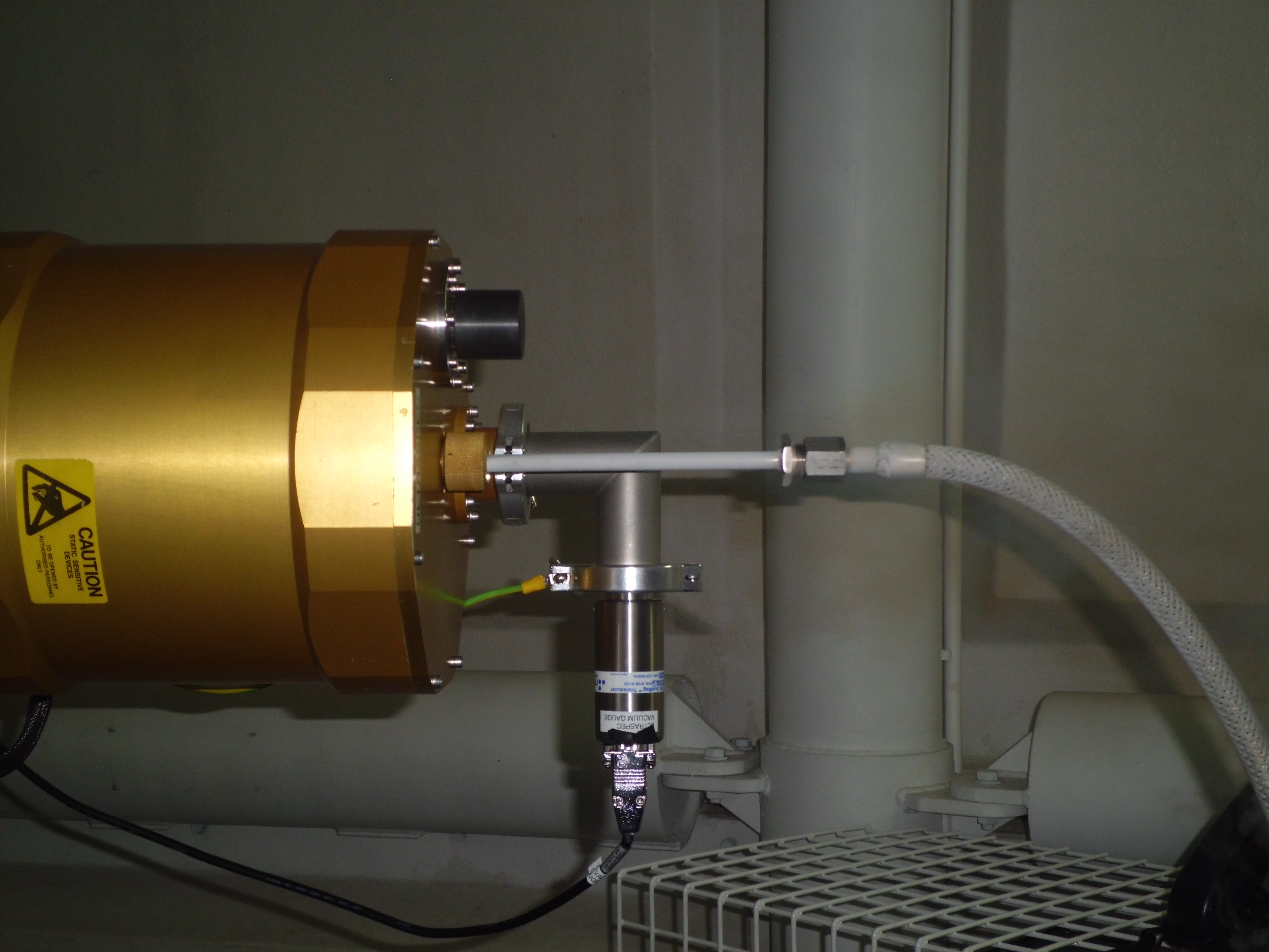
- Remove the valve cap covering the vacuum port on the end of the ULTRASPEC cryostat.
- Fully withdraw the plunger and then attach it to the cryostat
valve by tightening the large nut. To do this, the nut must be moved
anti-clockwise. You will know when you have attached the
plunger correctly, as it will not wobble and will rotate smoothly when
tested.
- Push down the plunger and when it stops, start screwing the black
knob in a clockwise direction. Keep doing this, watching the shaft
height reducing until you feel significant resistance. The shaft is
now fully engaged in the cryostat valve.
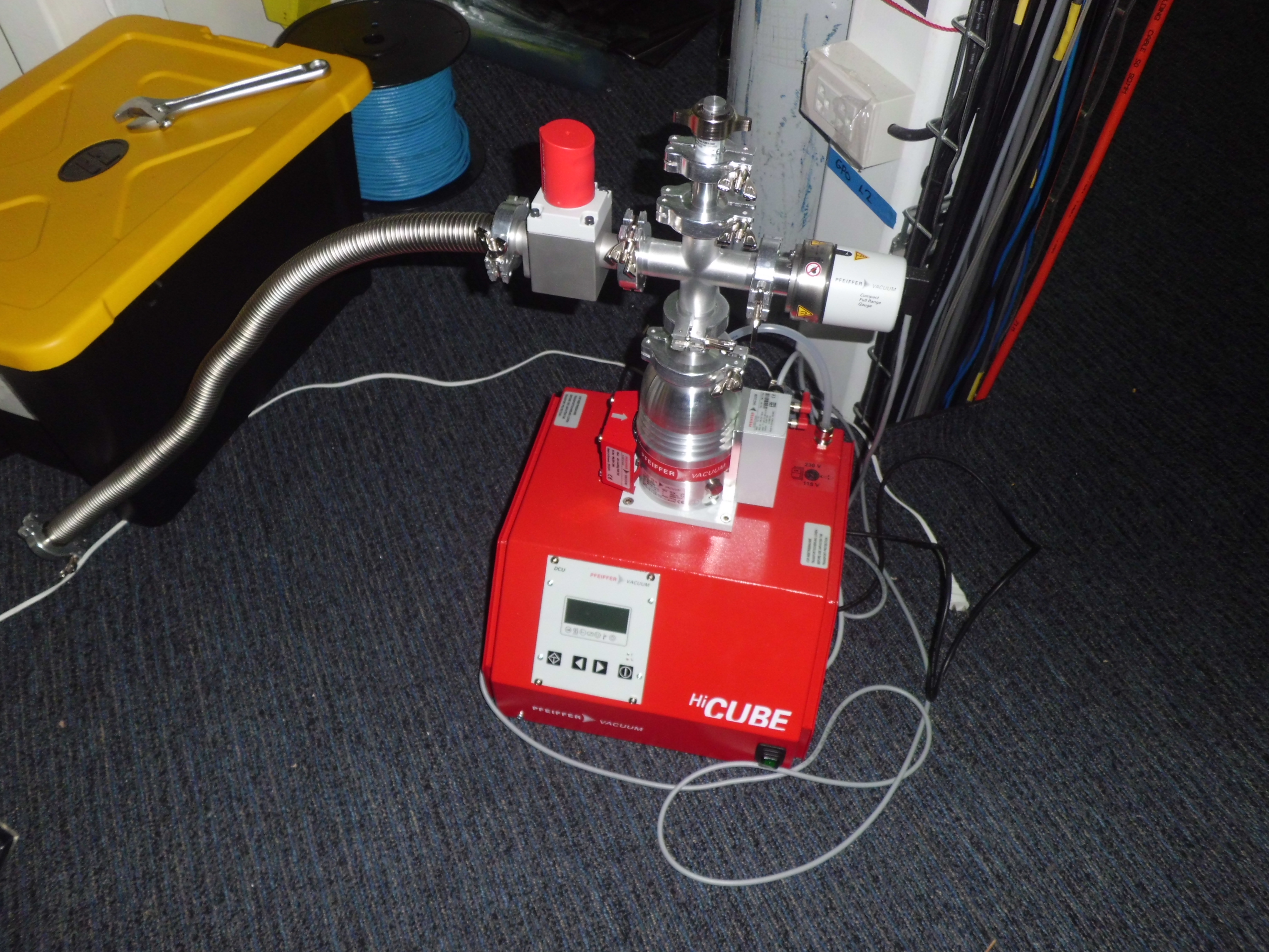
- Attach the flexible pipe from the red Pfeiffer vacuum pump to the
plunger valve, taking care to only touch the outer edge of the o-ring,
as any grease from your fingers can cause outgassing. Do not
over-tighten the clamps, as this reduces the effectiveness of the
o-rings. The pump and pipe should be positioned such that they exert
no tension on the plunger valve.
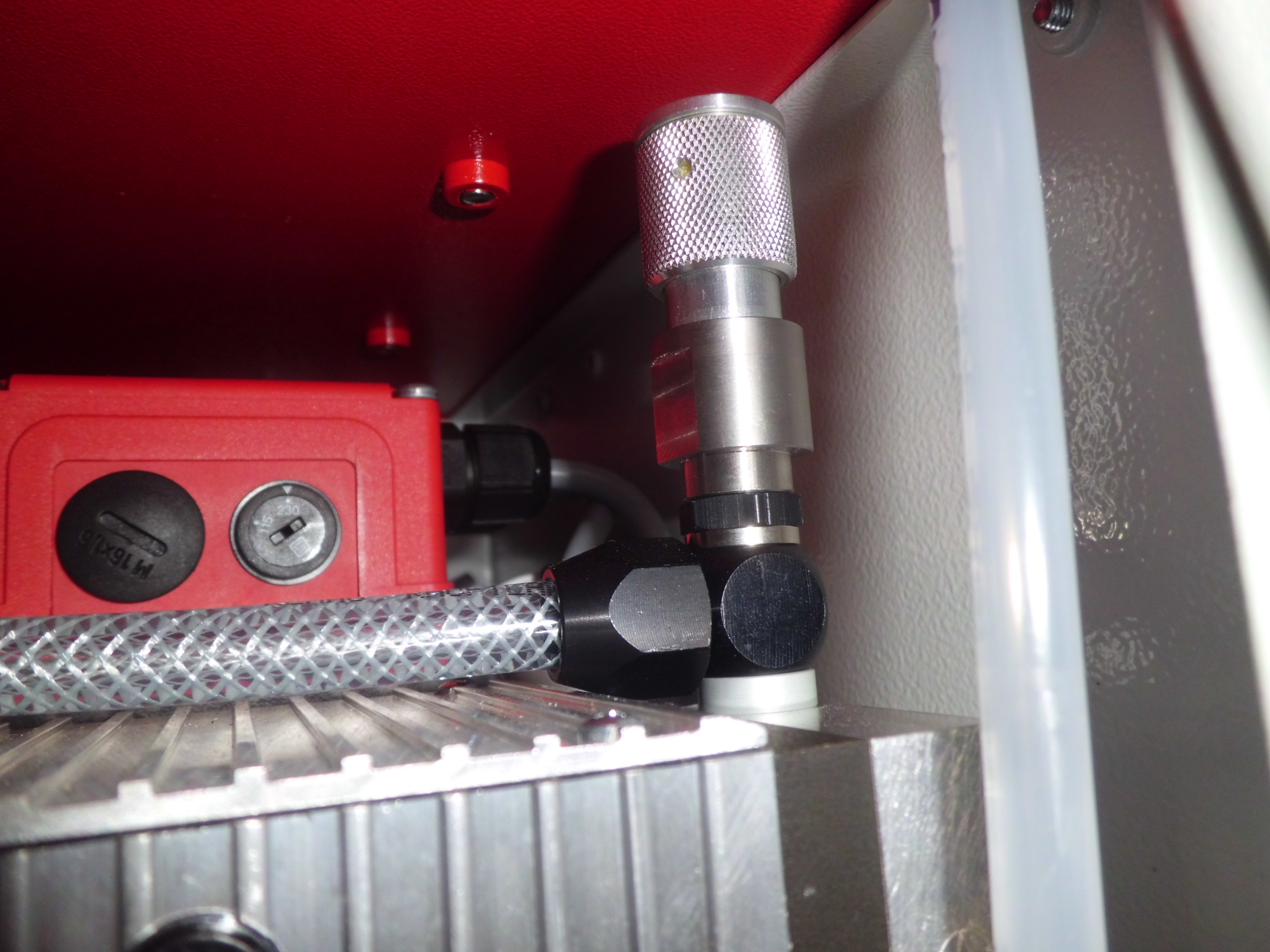
- Ensure the needle valve at the top of the vacuum pump is closed by
screwing it down anti-clockwise.
- Ensure that the large red isolating valve on the vacuum pump is
closed by turning it clockwise until it clicks.
- Ensure the gas ballast valve inside the vacuum pump is open. This
allows condensates, such as water vapour which collect in the pump due
to the humid environment, to escape.
- Switch on the mains power to the pump by pressing the green
on/off switch on the bottom right-hand side of the front face of the
unit.
- Activate the diaphragm pump by pressing the right-hand button on
the control panel.
- Ensure that the turbo pump is off by pressing the right-arrow
button until menu item 23 (MotorPump) appears. If it
is on, press both arrow buttons simultaneously, then press
the right-arrow button again until
off appears, and then press both arrow buttons again to set this
value.
- Once the pressure in the pump bottoms out around 4 × 100 mbar,
open the red isolating valve on the pump. The flexible pipe will now begin
evacuating.
- What happens next depends on whether or not the cryostat is at atmospheric
pressure. If the cryostat pressure is significantly lower than the pump
pressure, then opening the plunger valve will allow outside air to rush into
the cryostat, possibly contaminating the CCD. Hence the turbo pump must be on
in order to ensure the pump pressure is lower than the cryostat pressure.
Conversely, if the cryostat is at atmospheric pressure then opening the
plunger valve with the turbo pump running would overload the turbo, possibly
damaging it. Hence a different procedure must be used in each case.
- If the cryostat is at atmospheric pressure (103
mbar): With the turbo pump off, open the plunger valve. This
should be done smoothly and when fully withdrawn you will feel a
little click, at which point you should push it in by a
centimetre. The pump pressure will initially rise and then fall again,
settling at a value of order 100 mbar. Now turn on the
turbo pump, following the procedure outlined in step 12. You will hear a
whining noise and an inverted triangle will appear on the LCD display
above the far-left symbol. When the turbo reaches its maximum
frequency of 1500 Hz, another inverted triangle will appear on the LCD
display above the far-right symbol. The frequency of the turbo can be
viewed under menu item 309. The pressure on the pump will fall
rapidly, as viewed under menu item 340.
- If the cryostat is still under a partial vacuum (typically
10-1): Turn the turbo on (see step 12). When the pump
pressure reaches of order 10-6 mbar, open the plunger (see
above). The pump pressure will initially rise and then begin falling.
- After a few hours of pumping, turn off the gas ballast valve,
which prevents the lowest possible pressure from being obtained.
- Continue pumping until the pump pressure has reached of order
10-6 mbar and the cryostat pressure (which is always
higher) has reached of order 10-5 mbar. For examples of how
long this should take and the typical pressures achieved, please refer
to the
ULTRASPEC
detector page.
- Close the plunger. This must be done quickly and forcefully, with
significant strength required to push the valve fully in. Great care
must be taken to ensure that the plunger is fully closed. This is
probably the most difficult step of the pumping process, as most
inexperienced users do not fully close the valve. If performed correctly,
the cryostat pressure will then slowly begin to rise due to outgassing,
but it should not rise significantly above 10-5 mbar.
- Unscrew the black knob on the plunger by turning it anti-clockwise, watching
the shaft increase in length. When you feel the end of the shaft riding on top
of the valve, withdraw the plunger. The cryostat is now safe.
- Close the red isolating valve on the vacuum pump. The pump is now safe.
Power off the pump using the green on/off switch. The turbo will gradually slow
down and the pressure in the pump will gradually increase.
- Disconnect the pipe from the plunger valve, which will release the vacuum
in the pipe.
- Disconnect the plunger valve from the cryostat and replace in its
bubble-wrap bag.
- The cryostat should immediately be cooled down by filling with liquid
nitrogen, as described in the Afternoon activities, and the Lakeshore powered on, as described in Powering up
Powering up
A description of how ULTRASPEC's cables are connected is outside the
scope of this manual and it will be assumed that this procedure has
already been successfully accomplished. To then start ULTRASPEC from
cold, the following operations must be performed:
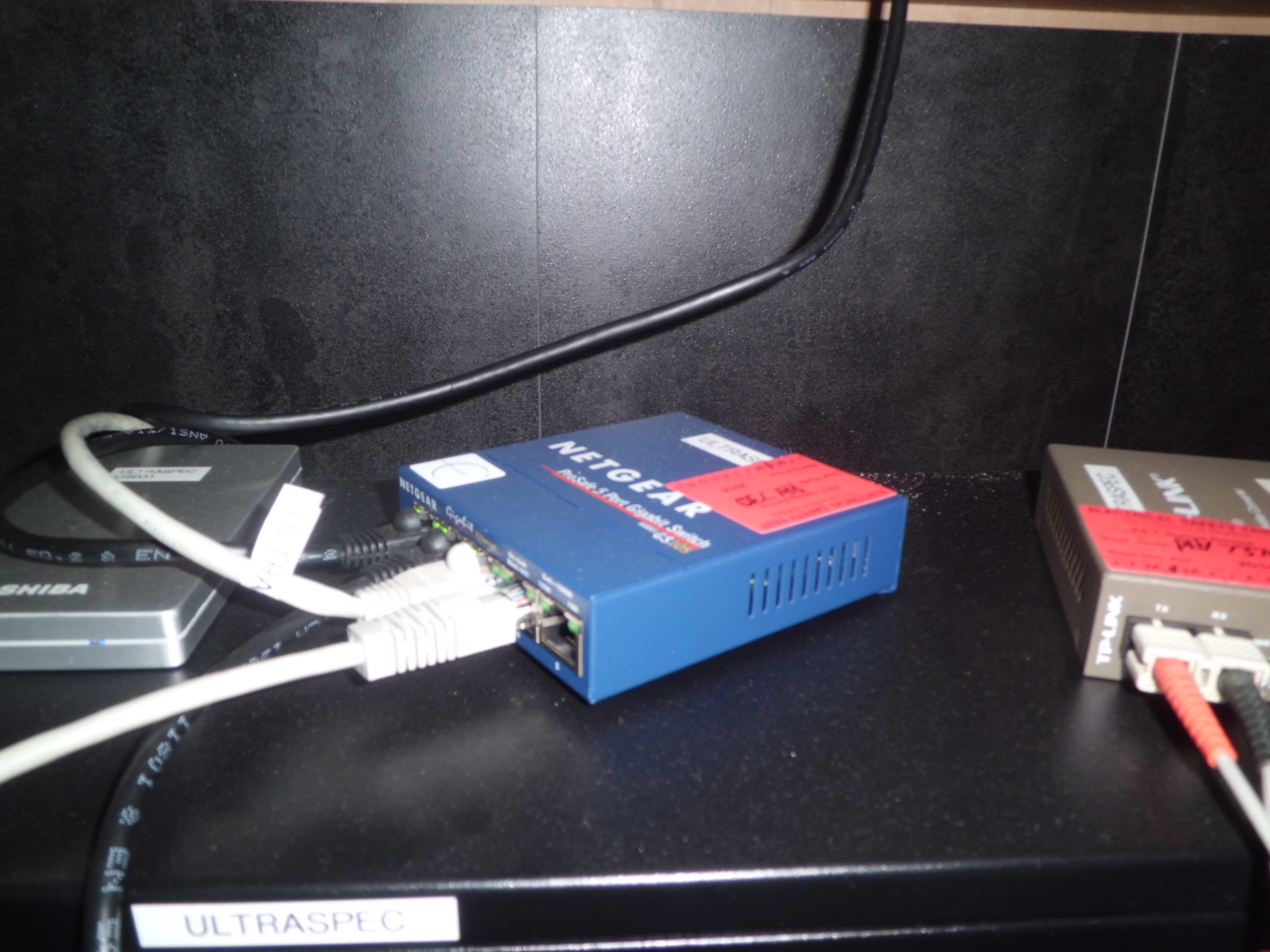
- Check that the ULTRASPEC network switch housed in the blue NETGEAR
box on top of the drpc in the control room is powered on.
- Turn on the drpc by pressing the large button on the front
of the PC.
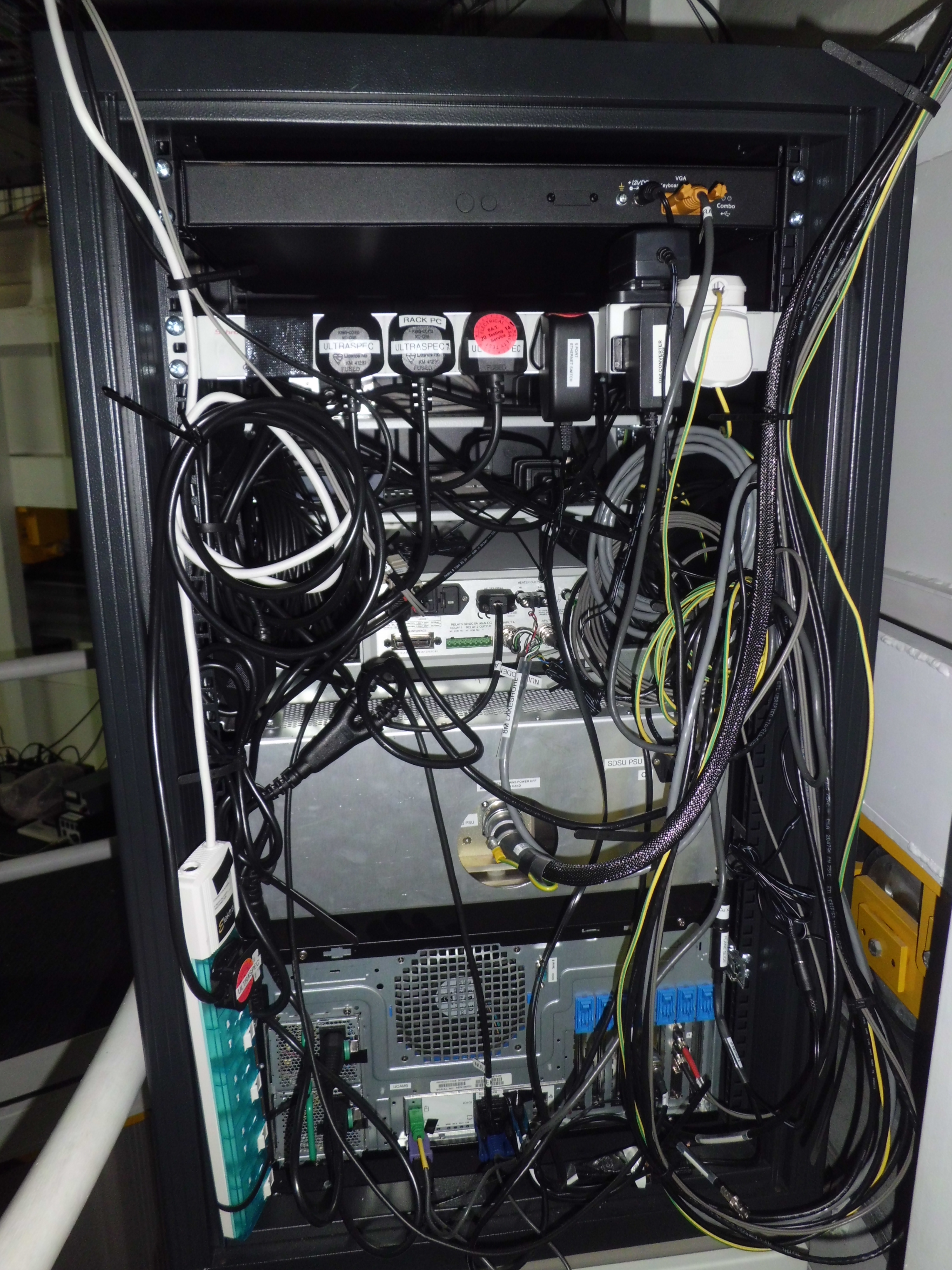
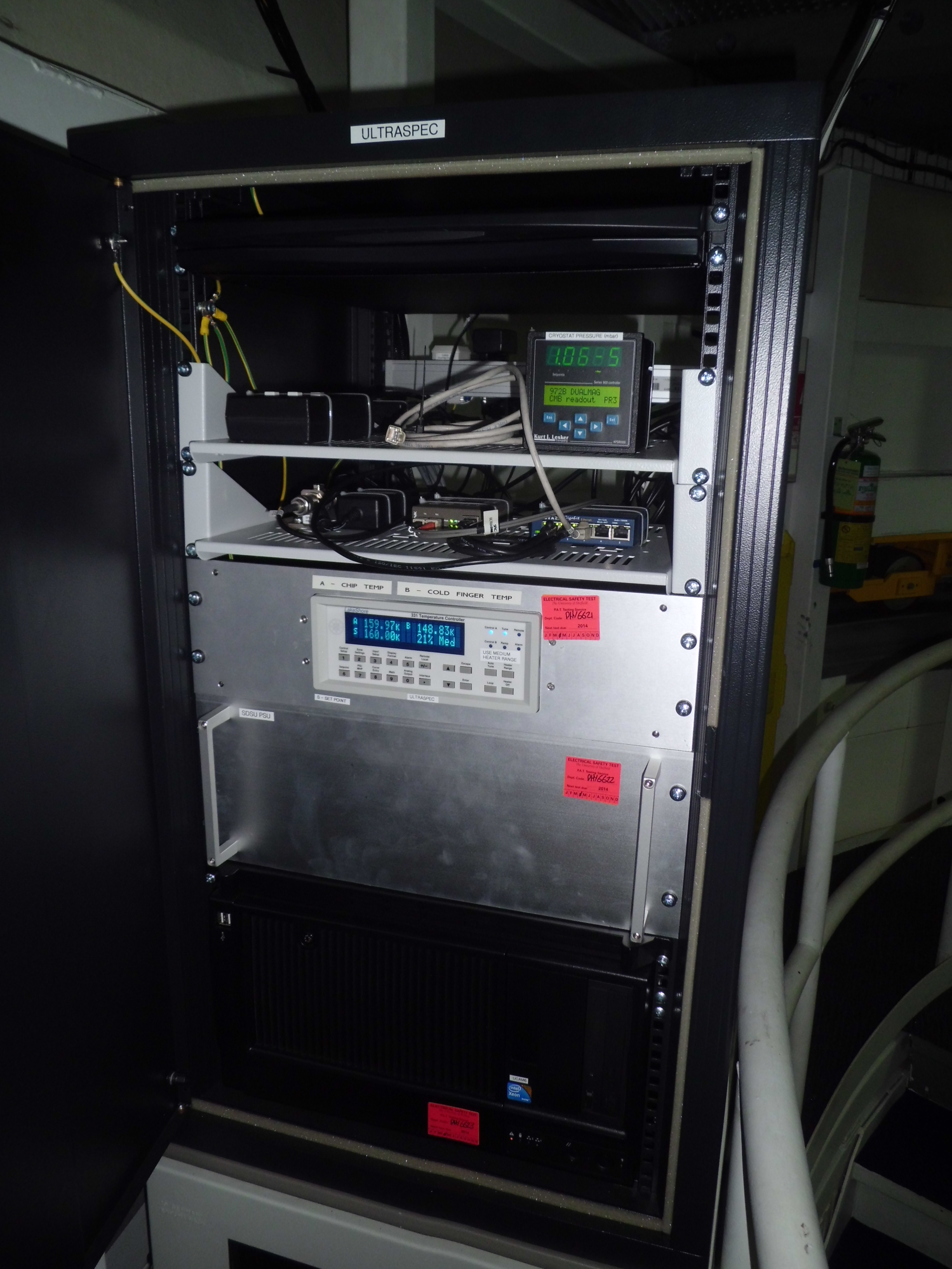
- Check that the green light on the mains socket strip at the top of the
rear of the electronics rack is illuminated - this
means that the rack is connected to the mains.
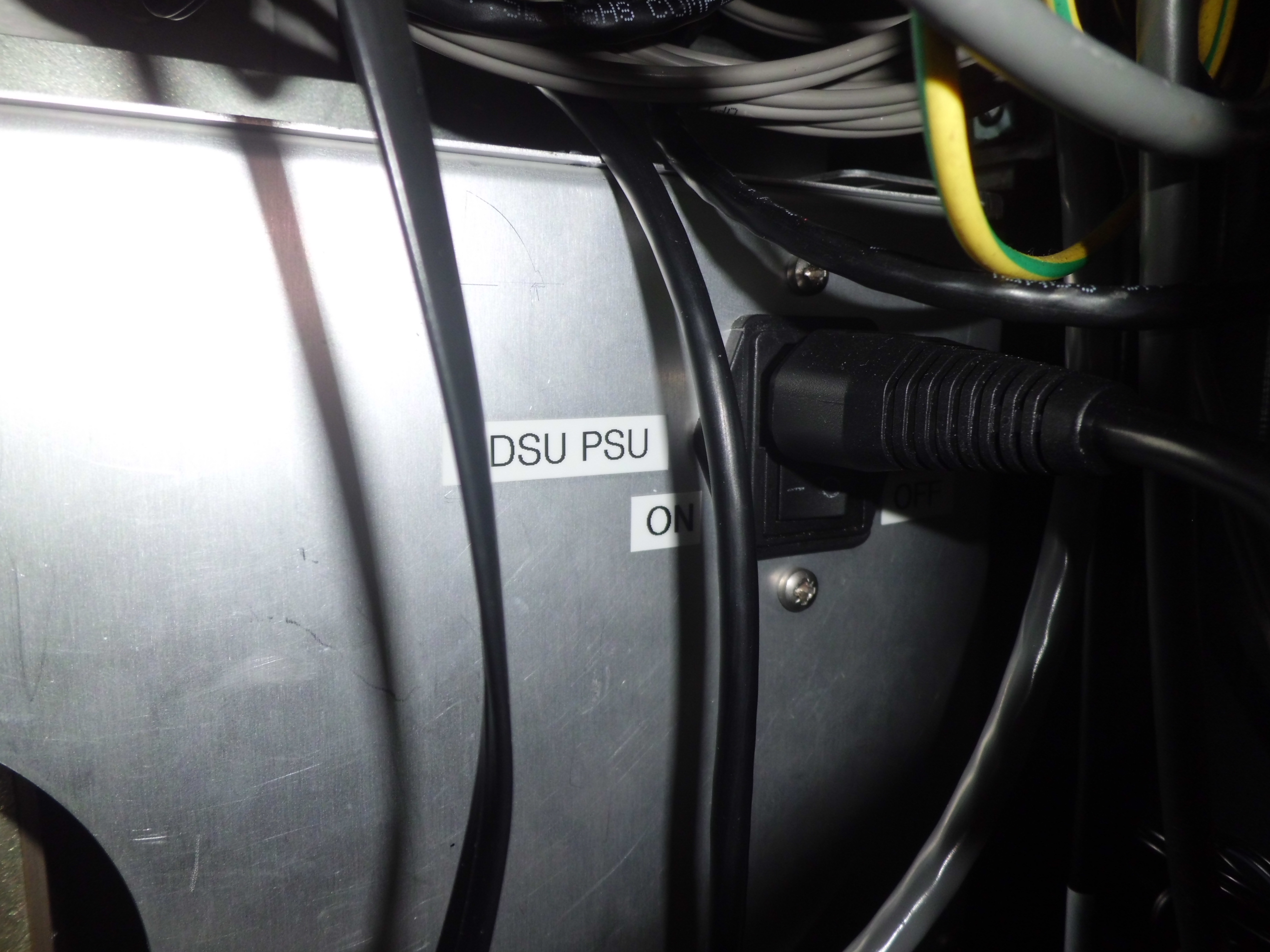
- Turn on the SDSU controller by
flicking the switch on the rear
panel of the SDSU PSU housing in the electronics rack. If successful, the fan
in the SDSU PSU should start up and two green LEDs should
illuminate on the front panel of the controller. If this doesn't work, check the fuses
(see the Troubleshooting section for
details).
- Turn on the vacuum gauge by flicking the switch on the rear of the display
unit on the top shelf of the electronics rack.
- Turn on the filter wheel by flicking the on/off switch on the black filter
wheel control box. The red LED display screen should flash the version number
(3.02) whilst it tries to home the wheel. Check that the filters can be changed
smoothly by pressing the 'next' button a few times, followed by 'home'.
If this doesn't work or the display gives an error, see
the Troubleshooting section for details.
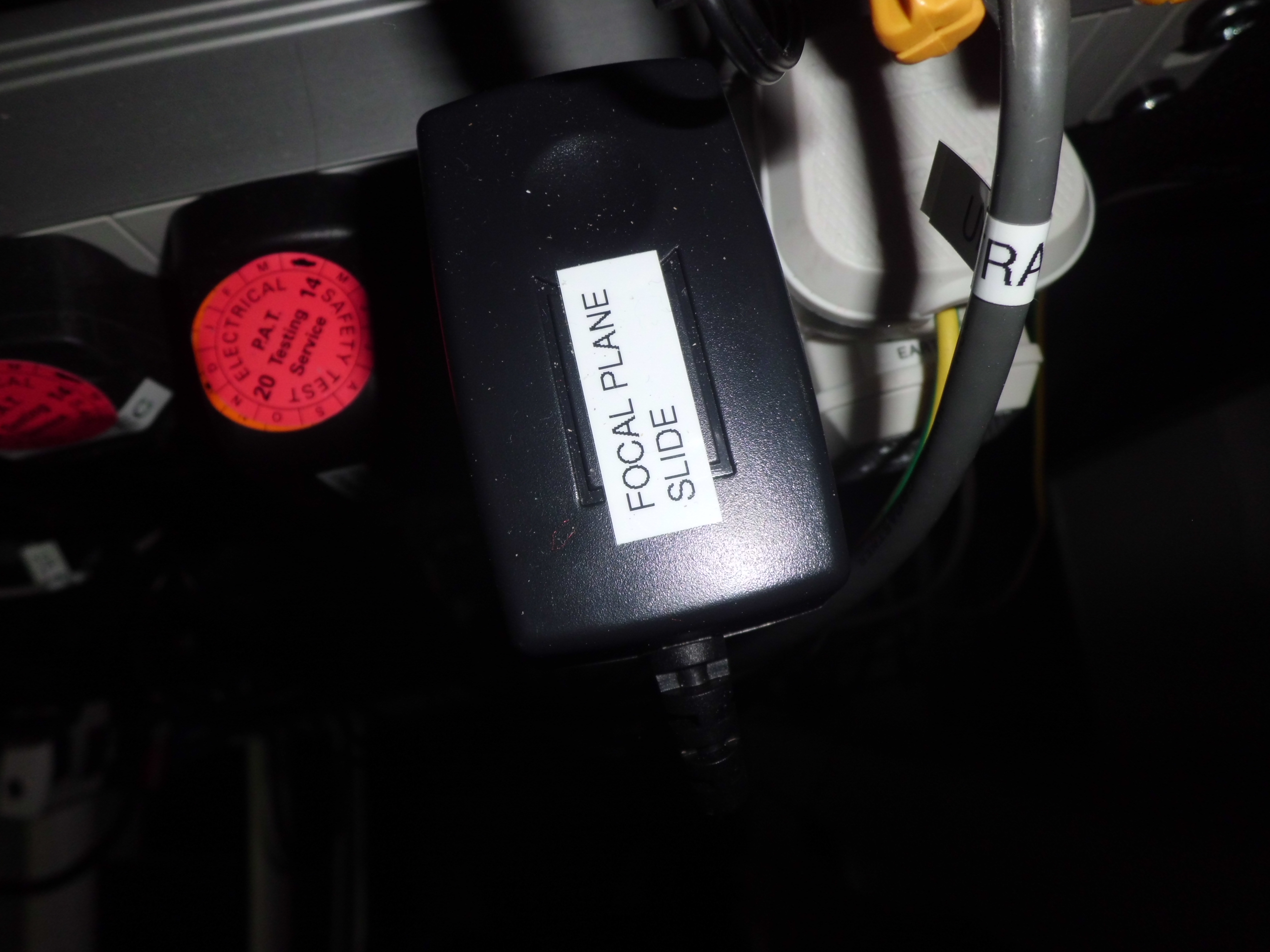
- Check that the focal plane slide power supply is plugged in.
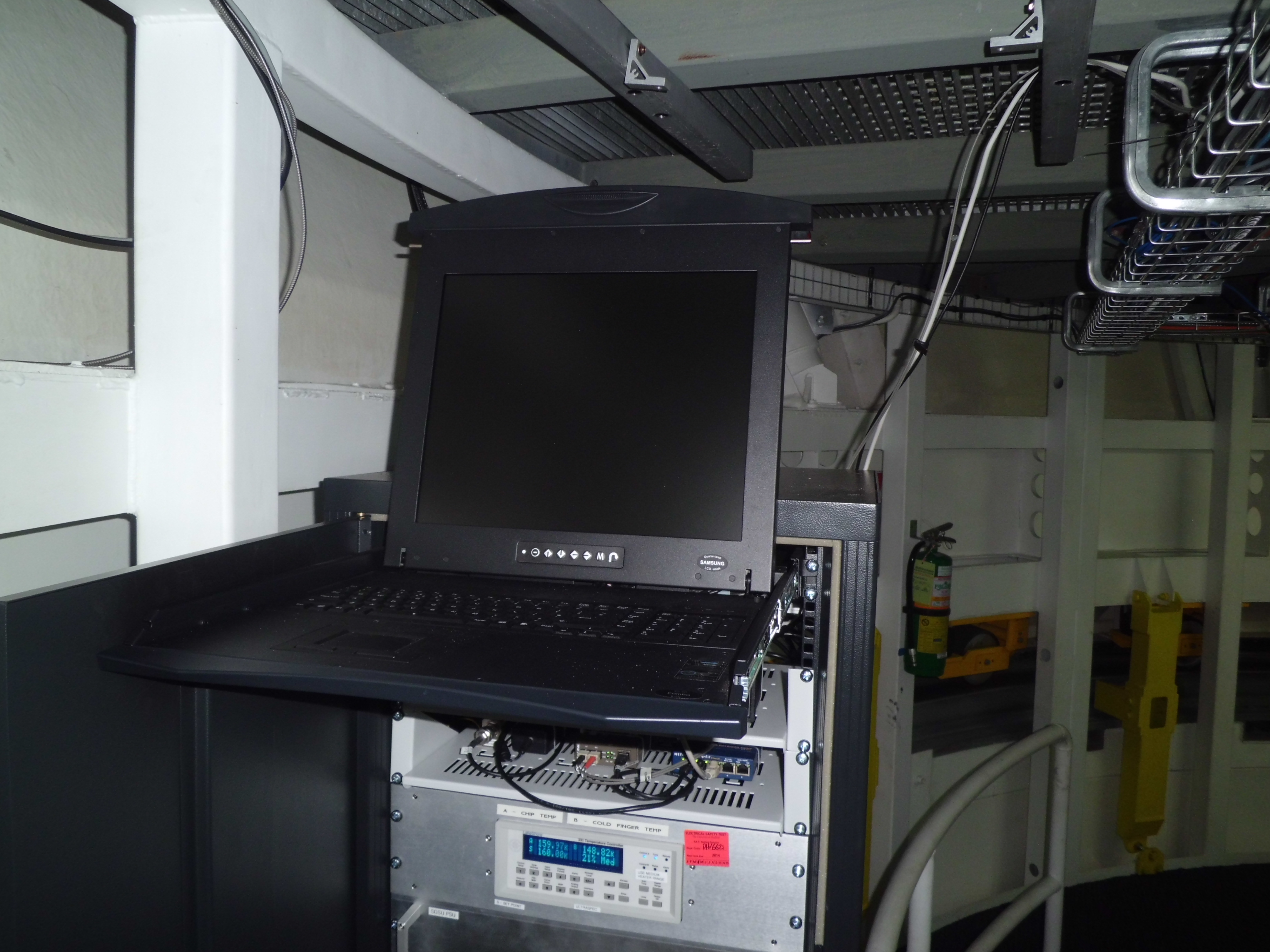
- Turn on the rack PC (housed in the black unit at the bottom of the
rack) by pressing the round button on the bottom right-hand side of
the front panel. Booting takes around a minute if the system was shut
down cleanly. If the PC is recovering from a crash, rebooting may take
longer than this whilst the system checks the disks. If you want to
see what is happening on the PC whilst it is booting, use the LCD
monitor on the sliding tray at the top of the rack; pull the catch
under the lid to release it (it is fairly stiff) and press the
left-most button on the monitor to power it on. Remember to turn the
monitor off again when finished, as it is a source of readout
noise. To stow away, release the two catches at the front left and
right-hand sides simultaneously and push in.
- Turn on the Lakeshore temperature controller, housed approximately
half way up the rack, by pressing the black switch from 0 to 1 at the
rear of the unit. The front display should illuminate, showing (clockwise
from top left) the CCD temperature, the cold finger temperature, the
heater power and the CCD target temperature. In normal operation, the
CCD temperature should be 160 K, the cold finger about 150 K, the target
temperature 160 K and the heater power should be in its medium range;
the percentage power value will vary between 0% and 100%, depending
on the temperature of the CCD relative to the set point. If the heater
power is off, you can set it by pressing the "Heater range" button until
the "Medium" setting appears, after which you should press the "Enter"
button. Never use the "High" power setting on the heater,
as this can destroy the chip. If you want to change the set point, press
the "Setpoint" button, then press the "1", "6" and "5" buttons (if you
want to change it to 165 K) and then "Enter".
Ideally, to ensure powering on the Lakeshore does not damage the CCD, Naidu
recommends we adopt the following procedure, which the UKATC adopted for
cooling the detectors in KMOS:
- The Lakeshore ramp should be set to ensure the temperature does
not change by more than 1 K/min.
- The heater power should be set to off by default when powering on
the Lakeshore.
- If there is a large difference between the set point and the
actual CCD temperature on powering on the Lakeshore, the heater will
come on at 100% power (the ramp is not initiated as the set point
hasn't changed). This is dangerous for the CCD. So go into the control
setup menu and turn off the ramp (this ensures the next step doesn't
take ages to complete). Then change the set point to a few
degrees below the current CCD temperature. Now turn on the
heater - it should give 0% power - and turn the ramp back on. Then
change the set point to the desired value. The heater will now come on
slowly thanks to the ramp, which is enabled as there has been a set
point change.
Powering down
During an observing run it is normal to leave everything turned on to
minimise the chances of failure from power cycling the electronics.
If, however, the power to the site is to be shut down, the system
should be powered down in the following order (refer to
the Powering up section for the location of
all relevant switches and devices).
- Ensure the observing system is shut down on the drpc
(see Before you go to bed).
- Turn off the SDSU controller.
- Turn off the vacuum gauge.
- Turn off the filter wheel.
- Turn off the Lakeshore temperature controller. This turns off the
heater which means that the chip will now start to cool even further
if the cryostat still contains liquid nitrogen. Once this boils off,
however, the chip will gradually begin to warm up. It is best not to
pump the cryostat during warm-up due to the low pressure that
ULTRASPEC achieves in its cryostat when cold - there would be a risk
of reverse pumping occuring due to the pump pressure being higher than
the cryostat pressure. The chip is always warmer than the cold finger
during a gradual warm-up, so there should not be any risk of
condensation onto the detector.
- Shut down the rack PC by typing "init 0" in an xterminal connected
to the PC or by using the sliding monitor and keyboard in the
electronics rack. This does not turn the PC power off, so when the
LCD monitor says "System halted" you should press the power button.
- Turn off power to the entire ULTRASPEC electronics rack by
switching it off at the mains.
- Shut down the drpc by selecting the Log Out
option from the Application Menu on the bottom left-hand side.
Then click the Shut Down button on the window that appears.
The PC will power down automatically on completion.
- Disconnect the white Thai-format power plug underneath the desk
where the drpc is located.
At the end of an observing run, when ULTRASPEC is not scheduled for use
for more than one night, please shut down the following:
- The rack PC - pull out the keyboard at the front of the rack. Login
as superuser (>su >password available on page 4 of Paul Kerry's
user guide to the ULTRACAM/ULTRASPEC computers) and type
init 0.
- When the system has halted, turn off the rack PC by pressing the
power button on the front.
- Turn off the SDSU controller using the on/off switch at the back.
- Swith off the black filter wheel control box on the
top shelf of the rack
- Unplug the power supply to the focal plane slide, which is plugged
into the white power strip at the back of the rack.
- Leave the drpc in the control room running, as this system is sometimes
accessed by ULTRASPEC team members remotely.
Afternoon activities
Before you start observing in the evening, you and/or the NARIT technical staff should do the following.
If you are remote observing, you can jump to item 6.
- In the dome, check the CCD temperature on the Lakeshore
temperature controller is stable and within 1 degree of 160 K.
- Check that the cryostat pressure is stable and 10-4 mbar
or lower.
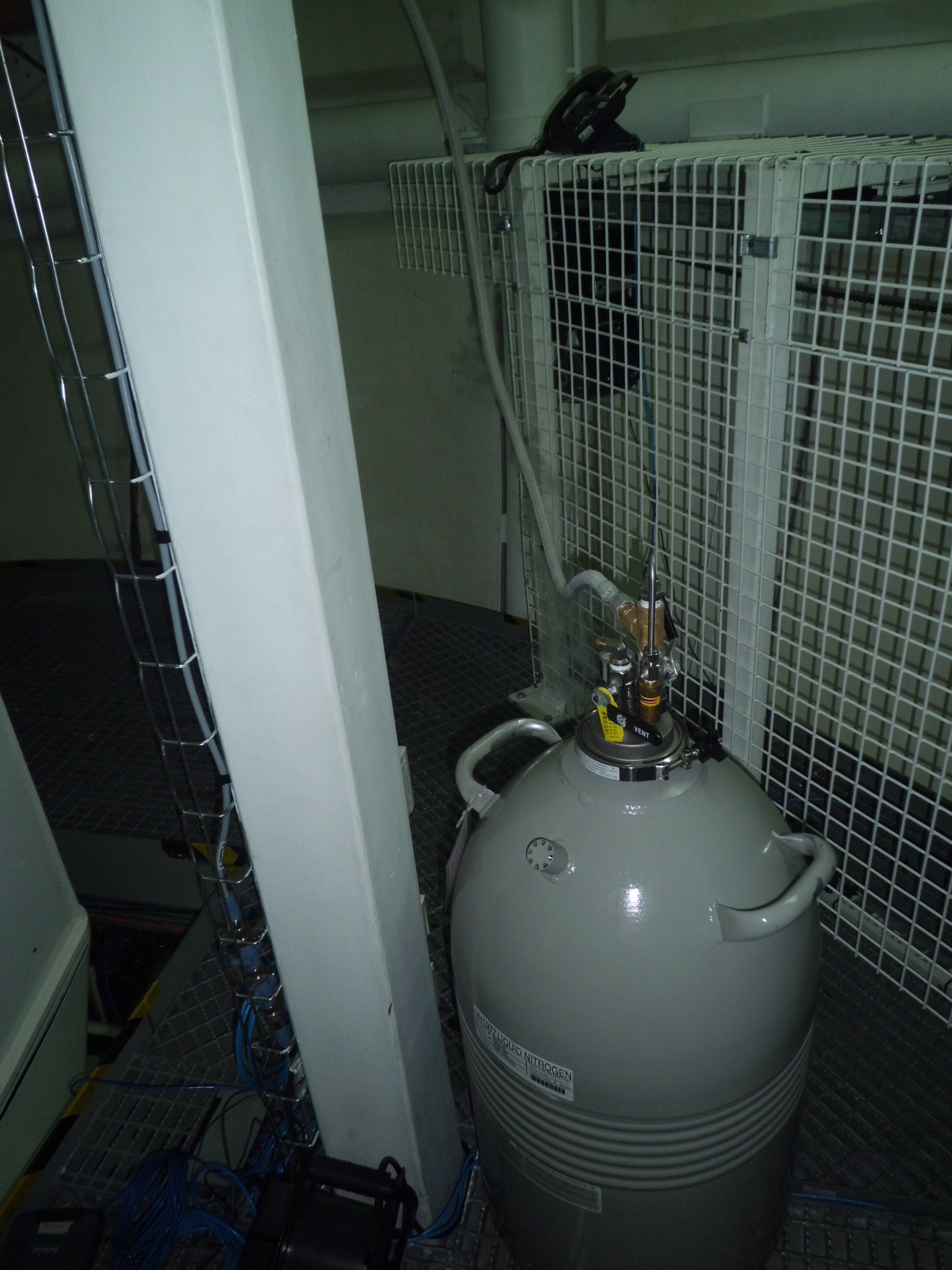
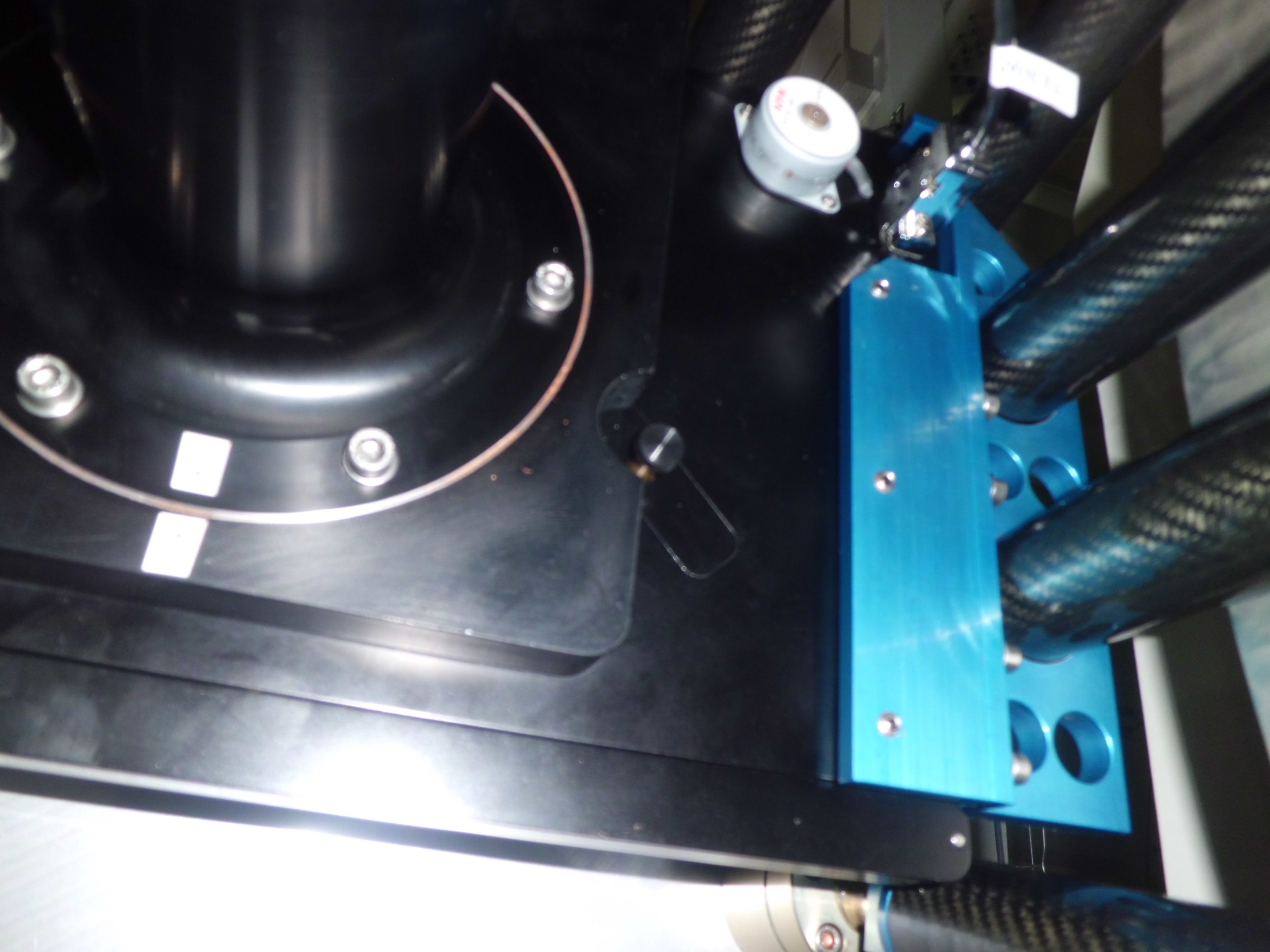
- Fill the CCD cryostat with liquid nitrogen.
First, position ULTRASPEC so that it is horizontal and on the
dewar side of the
Nasmyth focus. Then push the
Emergency Stop button and ensure no-one can access the floor below.
Donning a face mask and gloves, insert the
filler tube into the cryostat, and then
withdraw it by approximately 1 cm. Slowly open the valve on the
dewar. Depending on the pressure in the
dewar and the temperature of
the CCD, the cryostat will take 1-20 minutes to fill. When liquid
nitrogen begins pouring out of the filler tube, the cryostat is
full. Close the valve on the dewar, remove the filler tube from the
cryostat and carefully replace the filler tube in its holder on the
dewar. The hold time of the cryostat is approximately 20 hours, but
for safety it should be filled twice per day, once in the afternoon
before you start observing and once in the morning after you have
finished observing (see Before you go
to bed). Never fill the cryostat if the vacuum is
higher than 10-4 mbar. If this occurs, the chip must
be allowed to warm up, and the cryostat will need to be pumped down
prior to filling with liquid nitrogen (see Pumping down).
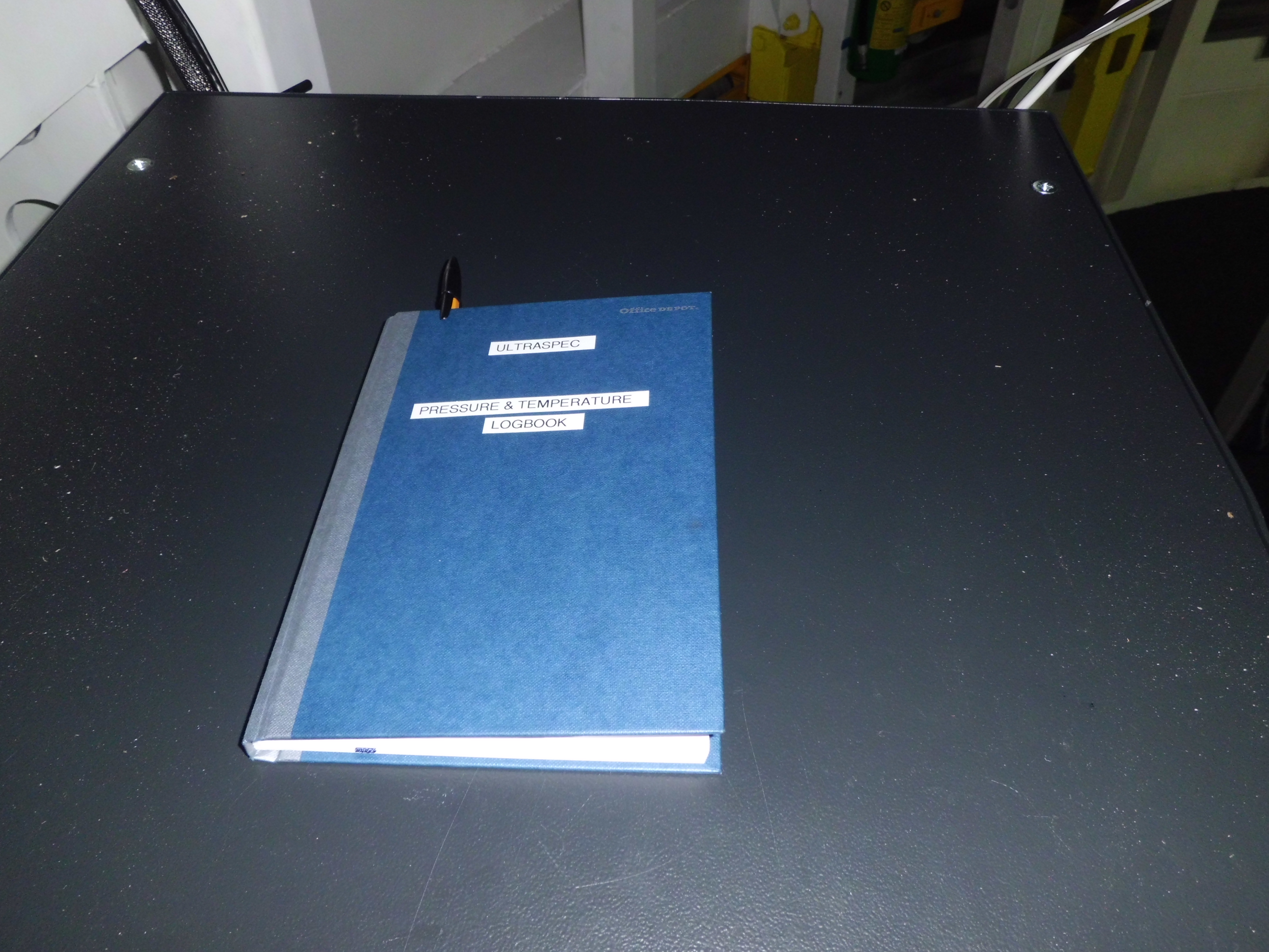
- Log the cryostat pressure, chip and cold finger temperatures, and
the time the cryostat was filled in the blue log book on top of the
electronics rack.
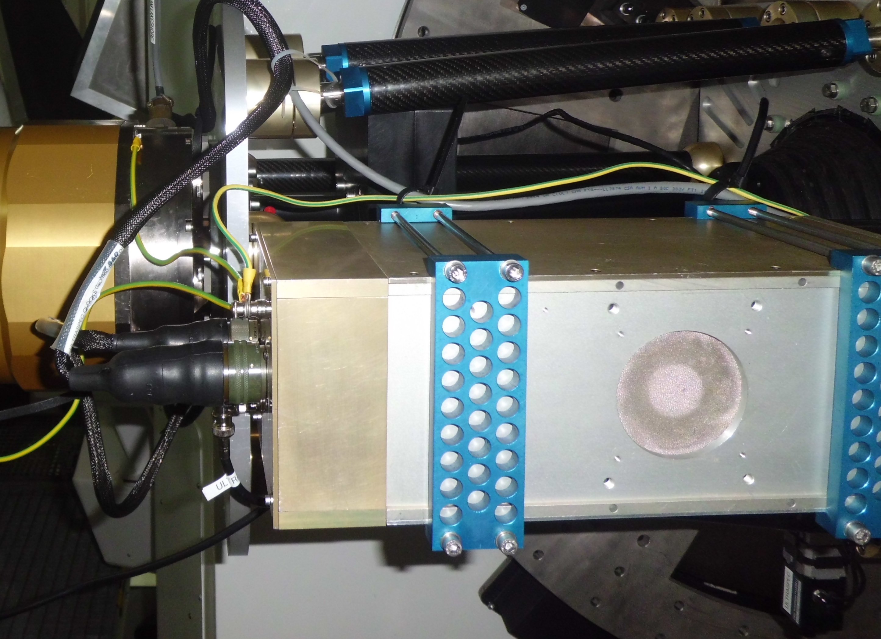
- Ensure that the cables running from the instrument to the
electronics rack are neatly arranged, show no signs of damage and are
not under any stress.
- Check to see if you need to make a filter change for the start
of the night. If you do, refer to Changing filters.
- Ensure all lights are turned off in the dome.
- In the control room, check that
the end_of_night_tasks script (run on the drpc) successfully
completed without error.
- Once you are happy that the previous night's data is safely
archived (see Archiving data for
details), check the contents of /data on the rack. This should
be empty of run files, which then ensures that the first run of the
coming night will be run001 (strongly recommended).
- Start the observing system (see Software startup).
- Take bias frames for all of the setups on the previous night (the
pipeline option missbias can aid this task) -
see Taking data. To ensure minimal light
falls on the CCD, ask the TO to turn off the dome lights, close the
primary mirror covers (if operational), and align M4 to a port other
than ULTRASPEC's, e.g. the 4k camera position. Also, ask the TO to
turn the air conditioning in the dome off, as this increases the
readout noise. Then position the focal plane
slide at pixel -100 (by pressing the block button in the
focal-plane slide menu on usdriver), and use the
lowest-throughput filter in the wheel, e.g. u'
or z'.
- Take some full frame bias frames in normal/slow (highest priority), normal/medium,
normal/fast unbinned and binned 2x2, time permitting. See
- Check the readout noise and bias level of the normal/slow bias
frames using the python quality control script. If using the HiPERCAM pipeline:
/home/observer/qc/ultraspec/uspec_qc_hicam.py, e.g.
/home/observer/qc/ultraspec/uspec_qc_hicam.py /xs
run002_002. If using the ULTRACAM pipeline, the corresponding command is: /home/observer/qc/ultraspec/uspec_qc.py. Whichever pipeline you are
using, you will first have to use the option grab to generate the required hcm (or ucm) files - remember to
delete these after use and/or generate them in a sensible location,
e.g. /home/observer/reduce/tmp. Note that if you try to grab data
that is not in the /data directory, you need to give the
relative path to the data, e.g. to grab run002 in a directory on
/data1, use the run name: ../data1/2019_02_27/run002.
The bias level should be
approximately 850 counts and the readout noise is usually in the range 5-6 counts
(but should ideally be 3.5 counts). Further details can be
found on the
ULTRASPEC
detector page.
- Check the sunrise / sunset times, e.g. using the
ING object
visibility page (selecting the Thai National Observatory
option).
- You can prepare for your planned observations using Stuart Littlefair's usfinder
tool. Click on the icon on the desktop of the drpc, and follow the instruction in the online manual to produce your
finding charts. You may need to re-size the window if you need to select drift mode.
Software startup
ULTRASPEC can be controlled from any Unix system connected to the
ULTRASPEC internal network (see
the Troubleshooting section for
details), although it is usual to use the ULTRASPEC drpc
in the control room.
- Login as observer to the ultraspec drpc in
the control room, if prompted. This machine has the IP address 192.168.1.1. If you
don't know the password, please contact one of the ULTRASPEC team
members.
- Open a window on the rack PC by double-clicking on
the rack icon on the desktop.
Alternatively, you can type rack or
ssh observer@192.168.1.2 in an xterm. You shouldn't need a
password to do this. If you need to know the password, please contact
one of the ULTRASPEC team members.
- Ensuring that the SDSU controller
is switched on, type the following in the xterm of the rack PC:
start_uspec
The following windows should then appear:
- The "camera" window
provides information on the commands used to control the
CCD, which are sent to the SDSU controller.
- The "filesave"
window provides information on the commands used to define
the quantity of data to be expected, which are sent to the SDSU-PCI card
in the rack PC.
- The python-based GUI (known as usdriver) sends the xml
documents containing the camera and filesave parameters to the SDSU
controller and PCI card via the http protocol. A small window will pop
up on starting the GUI which will prompt you for a log file name in
which to store the command history for that session. Give a filename
of the form, e.g. 2015_03_25_usdriver.log
- The "Fileserver" window allows users to access data files on the
rack PC. You can iconize this window when it appears.
- The "Lakeshore temperature monitoring" window which records
the CCD temperature every 10 seconds.
- Now power on the CCD controller by clicking on the "Initialise"
button in the "Instrument setup" box on the upper left-hand side of
the GUI. The filesave window should then report the creation of a
new run file in the /data directory. At the beginning of a
night, this should always be run001. If it isn't, close the
observing system down, clear the
/data disk, and restart the system. You are now ready to take data.
- If taking frames with windows which include the overscan regions, you may
wish to run the bias Checker program (the icon can be found on the
desktop of the drpc) which will display the read out noise of
each new frame taken by ULTRASPEC. It will flash red if the bias levels or
read noise are significantly different to the nominal values.
Taking data
To observe with ULTRASPEC, xml applications must be set up using the python
usdriver GUI and posted to the rack PC, before starting the exposures.
- If the previous configuration is still present and greyed-out,
click Unfreeze in the "Observing commands" box on the
upper-left side of the GUI.
- All non-greyed-out windows and options in the "Instrument parameters" and
"Next run parameters" boxes on the upper right-hand side of the GUI should be set accordingly for each run.
- The "Count & S-to-N estimator" box on the left-hand side of the
GUI can be used for rough signal-to-noise calculations in the 5 SDSS
filters, and also displays the calculated exposure times and frame
rates for the configuration set in the "Instrument parameters" box.
- Once you have entered the Target Name in the "Next run
parameters" box, you should verify that it is either available in
SIMBAD or in the ULTRASPEC target database by clicking
the Verify button. Remember also to click on the correct data
type button, and enter the ID, PI and observer details if not greyed
out. This aids the data logging procedure.
- To change numbers in the boxes, you can left-click to add one, right-click to subtract one, press
PageUp to go to the maximum allowed value, PageDown for the minimum,
Shift-left/right-click to increase/decrease by 10,
Ctrl-left/right-click to increase/decrease by 100, or type the
required number manually. To take an unlimited number of exposures, set the
Num. exposures box to 0.
- When you are happy with the configuration, click Start in the
"Observing commands" box. You should see the frame counter increasing in the
filesave server window, unless you are running in quiet mode
(see Drift mode).
- Click Stop if you wish to finish exposing before the requested number of
frames have been taken.
- If there is any chance you might return to the same target in the
future, it is useful to save the configuration settings by clicking
the Save button in the "Observing commands" box. The
application with all the settings (e.g. binning, window sizes,
exposure delay etc) can then be loaded next time by clicking
the Load button. All applications should be stored in
the /home/observer/.usdriver/apps directory.
Looking at data
As of December 2019, you can use the python-based
HiPERCAM
pipeline reduction software. This is now the recommended method of
looking at ULTRASPEC data, as the ULTRACAM pipeline is no longer
supported. You can still use the ULTRACAM pipeline if you need to -
instructions on how to do this are given below.
Running the HiPERCAM pipeline requires the same FileServer to be
running, but no initialisation command is required to start the
pipeline. Please ensure that the real-time data reduction performed on
each night is stored in a directory of the form
/home/observer/reduce/yyyy_mm_dd on the drpc. Please also
ensure that all output files from the pipeline are named according to
the run number being reduced. So the standard reduction sequence using
the HiPERCAM pipeline would be:
- averun - input run00x.dat, output run00x.hcm
- setaper - input run00x.hcm, output run00x.ape
- genred - input run00x.ape, output run00x.red
- reduce - input run00x.red, output run00x.log
There is a new defect file made specifically for ULTRASPEC when using
the HiPERCAM pipeline on the drpc - it can be found
in /home/observer/reduce/defects/defect_hicam.dft. The
defects can be over plotted when using the command rtplot, to
help you avoid placing targets or comparison stars on bad pixels. The
red/yellow dots show pixels which suffer more than a twenty/ten
percent decrease in responsivity in flat fields.
Please tidy up the /home/observer/reduce/yyyy_mm_dd directory
at the end of each night, as it is now archived along with the raw
data by the end_of_night_tasks data-archiving script
(see Archiving data for details).
If desperate, you can still use the ULTRACAM pipeline reduction
software to look at ULTRASPEC data either in real-time or off-line -
see the
manual for details. The details given in the rest of this section
below refer only to the ULTRACAM pipeline, not the HiPERCAM one.
First, open a terminal on the drpc by clicking on
the drpc icon on the desktop. The latest version of the
software can be initialized by typing the following command in the terminal:
ultracam9.16
If you have problems running this version, type ultracam
followed by a tab, which will show you all of the versions currently
available on the drpc.
You can then type any of the pipeline reduction commands, e.g.
rtplot. A useful introduction to the ULTRACAM pipeline is Tom's
Getting Started page.
There are three defect files available which can be over plotted
when using the command rtplot, to help you to avoid
placing targets or comparison stars on bad pixels. They can be
found on the drpc at:
/home/observer/reduce/pre-commissioning/defects/tenpercent.dft
/home/observer/reduce/pre-commissioning/defects/twentypercent.dft
/home/observer/reduce/pre-commissioning/defects/ten+twenty.dft
The first displays pixels which suffer a ten percent decrease in
responsivity in flat fields, the second shows those pixels with twenty
percent responsivity drops, and the third plots both. Small red dots
represent ten percent loss pixels, larger red stars indicate twenty percent
pixels.
If you wish to convert the .ucm files on the rack to .fits files:
- On the drpc, go to the directory where you want the FITS files to be written.
- Check that the FileServer is running
- Type tofits.py -u run015
- This will produce a sequence of files named run015_1.fits etc
- To see more options type tofits.py -h
To wish to convert the .ucm files on the rack to 3D FITS files:
- As above, but type to3dfits.py -u run016
- This will produce a multi-layered FITS file for each window named run016_1.fits etc
- To see more options type to3dfits.py -h
These programs will also create ASCII files named run***.times with the GPS
timestamps at the centre of each exposure.
Logging of data
slogger is a c-shell script which produces a log of ULTRASPEC
observations on a web browser. slogger also provides status
information on the current run, outputting an audible and visual alarm
if the CCD temperature rises above 165 K, if the GPS stops working and
if the file size goes over a user-defined limit. Please refer to the
Troubleshooting section for advice on
how to deal with the problems reported by slogger.
The slogger script runs in real time on the rack
PC. The script works by polling the directory containing the data
(usually /data) and extracting information from all the xml
files it finds. For each ULTRASPEC data file, it also determines the
start/end times, file size, number of frames and exposure
time. Comments on each run are input using an optional comments file,
which must reside in the same directory in which slogger is
run. An example of the optional comments file can be
found here - it is essential that you
do not change the format of the file, i.e. the two header lines and
the order of the columns. The easiest thing to do is to use a copy of
the previous night's file for the new night. Any keyboard character
can be used in this file except < and >.
To run slogger whilst observing on 2013_11_05, open a new rack PC
terminal and type the following:
cd /home/observer/slogger
emacs 2013_11_05_log.dat & - and enter the run number and
comments for any runs already taken.
slogger
> /data (the directory on the rack PC to which data is written)
> 2013_11_05_log (the name of the log file - omit the .dat)
> 6000 (the file size at which you wish the alarms to go off)
> y (to test the speaker volume level)
(slogger /data 2013_11_05_log 6000 y
typed on the command line will also work.)
The script will run indefinitely, polling the data directory a few
times every minute and looking for changes in either the data files or
the comments file. If it finds a change, it will update the log
displayed on the web browser. To exit slogger, just type
crtl-c, but only do this when slogger says
that it is safe to do so. The final log is written to a file in
html format - in the example above the resulting file would be
called 2013_11_05_log.html.
slogger can also be run off-line (i.e. when not observing) on the rack
PC in exactly the same way as described above and can be used to poll
any directory on the rack PC containing ULTRASPEC data.
Note the difference between the Pre-run comment that can be entered in
usdriver and the comments that are entered in
the slogger comments file. The former are written once only
at the very start of a run. The latter can be changed at any point
during or after a run, and hence should be used as the primary source.
Observing
- FLATS: The first observations of the night (after evening
bias frames) will typically be sky flats. Point to a blank field,
ideally near the zenith. A list of fields can be found in the red
ULTRASPEC folder, and the TO should also have a list. Ask the TO to
offset the telescope in steps of 10 arcseconds every 10 seconds or
so. This ensures that any stars appearing in the sky flats do not
occupy the same space on the image from frame to frame. The TO
should have access to an automatic spiralling script to do
this. Make sure the telescope is not pointing near the moon, and try
to avoid clouds if possible. Try to get at least 10 frames in each
filter you intend to use (20+ ideally), with roughly 20,000 - 50,000
mean counts in each frame. Less than 20,000 and the flat fields may
introduce more noise than they can account for, and above 50,000 the
chip sensitivity is less linear. In the evening, the sky is
darkening fastest at blue wavelengths, so begin with narrow band
and/or blue filters, and move through to redder filters. Reverse
this order for morning sky flats. If you miss sky flats, consider
taking dome flats instead. Point the telescope to elevation 41 or 71
degrees (these correspond to the most uniform regions of the
shutter) and turn on the lower level lighting only.
- STANDARDS: If the conditions are photometric, observe a
flux standard star. A printout of the
Smith
et al. (2002) SDSS standard stars is available in the red
ULTRASPEC folder, and Alex Brown's list of ULTRASPEC standard stars is available
here.
- FOCUS: Use the standard star or the first science target to
check the telescope focus. Begin a series of exposures and reduce the
data (see Looking at data) to plot the
FWHM. Step the telescope focus in units of 0.03 mm around the nominal
focus position (-0.83) until you find a clear minimum.
- ACQUISITION: Check that the TO has removed any pointing
offsets for each new target that you slew to. For each science target,
use the acquire run type in the usdriver GUI and
take some frames to check the count levels, position and orientation
of your target(s). Be sure to avoid bad pixels, which can be
overplotted when using rtplot. Check the rotator limits (-244
and +255 degrees). If the rotator might hit the limit before you
finish on this target, consider asking the TO to rewind 360
degrees. To tweak the telescope position, it is best to run the script
/home/observer/bin/tweakPointingNew, which you can also
launch by double-clicking on the tweakPointingNew desktop
icon. This script prompts for the desired x,y pixel offsets
and current rotator PA, returns the required offsets in arcseconds in
N/S/E/W, and then sends these offsets (in radians) to the telescope,
if required (or you can just say no and ask the TO to make the
offsets). Remember to use spaces between the 3
parameters, not commas, and to hit "y" when prompted to actually move
the telescope. If the new script fails for some reason, run the
old manual one,
/home/observer/bin/tweakPointing, and ask the TO to make the
offsets for you. When you are happy with the setup, start a new run
using the data run type.
- OBSERVING: Setup the live reduction as soon as possible,
and use it to keep an eye on transmission, x and y-pixel offsets, and
the seeing. Keep a close eye on the plotted images, and be on the look
out for tracking or rotator glitches, which are common at the TNT.
It is recommended that you autoguide using the science frames. To do this,
you can use the autoguide python script in
/home/observer/bin on the DRPC. This takes as inputs the
reduce log filename, the aperture number you want to autoguide on,
the bin duration in seconds that you want to average the data over
for autoguiding (typically about 30 secs), and the sky PA in
degrees, e.g.
python3 /home/observer/bin/autoguide /home/observer/reduce/2020_02_25/run005.log 2 30 270. You must make sure that you have started a reduce and it has
caught up with the latest data frame prior to starting the autoguide script.
It is essential to note that the autoguide script will only work with
reduce log files output by the HiPERCAM data reduction pipeline!
Remember also to keep a detailed log of each run for the slogger
(see Logging of data).
Note that the elevation
limits at the TNT are:
- With the front shutter down (parked), you can observe with elevations
between 40° and 89°.
- With the front shutter raised, you can observe with elevations
between 30° and 70°.
Drift mode
To obtain the highest frame rates it is necessary to use drift mode,
where CCD windows are stacked up in the masked region of the frame
transfer chip. A full description of the algorithm is given in the
ULTRACAM MNRAS paper. Generally speaking, it is best to use drift
mode when you require approximately 10 Hz frame rates or higher, as
otherwise the dead-time due to frame transfer across the 1024 rows in
the masked region (which takes approximately 24 milliseconds) becomes
a significant fraction of the exposure time.
To take data in drift mode, it is recommended that the observing system is
started (see Software startup) with the
"-q" (for "quiet") option as follows:
start_uspec -q
The above command suppresses the frame number from being written
to the filesave window, reducing the demand on the data reduction
PC. It is recommended that you do not overload the rack PC, data
reduction PC and ULTRACAM internal network with non-essential tasks
when running in drift mode at the highest frame rates in order to
minimise the chances of crashes.
If the sky is bright, you might notice that the top part of a window
has a different background level compared to the bottom half. This
occurs when it is impossible to fit an integer number of windows in
the image area and hence part of each window exists on the chip (and
hence accumulates sky) for slightly longer than the other part. To
negate this effect, put the focal plane mask in the beam. The
focal plane mask can also be used to prevent bright stars lying on the
same column as your target star but on a higher row from corrupting your
image. The slide is also useful if you want to minimise the light falling
on the chips when taking bias frames and darks.
The focal plane mask is most easily moved from usdriver by
pressing the Focal plane slide button on the upper left-hand
side of the GUI. Enter the requested y-pixel postion and
click goto. When you have finished this target,
click unblock to return the slide to its default position, just
outside the view of the CCD.
Setting up for drift mode can be quite tricky - it is recommended
that you use setup windows in rtplot to assist you. You can then
take full frame images and plot the positions of the drift mode
windows in rtplot, allowing you to move the stars into the centres
of the windows. Note that you have to use http://192.168.1.2:5100
for the name of the setup windows file in rtplot.
Changing filters
Only attempt a filter change if you have been shown how to do so by
trained NARIT staff or a member of the ULTRASPEC team.
- First, locate the filter(s) you wish to insert into the 6-position
filter wheel. These should be found in the wooden boxes in the glass-doored
Dry-Cabinet inside the TNT dome. Also locate the air blower and blue gloves in the
optics cleaning box, and the small, magnetic Philips screwdriver in
the toolbox, all of which are located in the ULTRASPEC cabinet
in the dome.
- Turn off the filter wheel
control box. Unscrew the fastening bolt on the side of the
filter wheel housing, being careful
to catch the little washer on the end of the bolt. Open the
filter wheel door and, holding
the edge of the filter wheel, unscrew the central bolt keeping the
wheel in place. Carefully slide out the
filter wheel, taking great care
not to let anything touch the filters. This is best performed with gloves on.
- Lay the filter wheel down on a clean surface.
- Take out the filter you wish to replace by unscrewing the small screws holding
it in place. Be very careful not to drop the screws onto the filter.
- Check the air blower is blowing clean air by spraying it first
onto your hand. When the flow is definitely clean, blow off any dry
residue or dust from the filter. If using a compressed-air canister, make sure
you do not shake it prior to spraying on the filter, and always hold it upright.
- Return the filter to its correct position in the filter box, carefully storing it inside
its labelled pouch.
- Place the new filter in the empty position. It does not matter which way round
the filters go.
- Replace the small black tabs and screw the filter in place, being
very careful not to allow the screwdriver to slip off the head. Check that
the filter is not loose by picking up the wheel and gently shaking
it. This is a particular problem with the KG5 filter. If
loose, use one of the square plastic shims located in the wooden
filters box in the Dry-Cabinet or the cardboard filter-wheel box in
the ULTRASPEC cabinet.
- Repeat for any other filters that need changing.
- Use the air blower again to blow off any dust before returning the filter
wheel to the housing. The side of the filter wheel with text should face towards
the ULTRASPEC cryostat.
- Carefully slide the filter wheel into the housing, and then tighten the central bolt
until you cannot pull the wheel out again. Try rotating the edge of the wheel to make sure
it is securely located - if difficult to turn, it could be that you have overtightened the
central bolt (although make sure the power is off to the filter-wheel control box, as this
can also cause resistance to motion).
- Close the filter wheel door, making sure you place the washer on the bolt between the door
and the housing. Firmly tighten this bolt.
- Turn on the filter wheel control box (see Powering up).
If there are any problems, see the appropriate Troubleshooting section.
- Note down which positions hold which filters, and use this mapping to update
the filter options on the usdriver GUI. Click Filters from the
top bar, then Edit filters.
Archiving data
At the end of the night, ensure that slogger
has been correctly shut down and that data taking has completely
finished.
Make sure that the USB disks are mounted by typing df in a
drpc terminal. If they are not mounted, right-click on their
desktop icons on the left-hand side of the screen to mount them.
Run the script end_of_night_tasks from the drpc.
This archives the original data, which is stored in /data on
the rack PC, to two large-capacity USB disk drives in the
control room. The script also makes a copy of the data on the
archiving disk /data1 in the rack PC, and a
subdirectory of /data. Critically, this script also corrects
for an intermittent timestamping error. When such an error is found,
the data file is automatically corrected, and a copy of the original,
uncorrected file is made with a filetype .dat.old. The script
is self-explanatory to run.
Before you go to bed
- Make sure that the slogger logs are up-to-date and complete for the night.
- Shut down the observing system by closing usdriver
using "Quit" on the top bar, and typing ctrl-c in the
filesave and camera windows (in that order).
- Close down the Lakeshore temperature monitoring by
typing ctrl-c in the Lakeshore window. This ensures a new log
file is created each day, and hence helps to prevent the creation of
very long files which are difficult to search through when problems
with the CCD temperature occur.
- Archive all data obtained during the night
(see Archiving data).
- Fill the CCD cryostat (see Afternoon activities).
- Go to bed.
Troubleshooting
start_uspec does not bring up filesave and camera windows
This problem will occur if the observing system is already running.
It may also occur if the SDSU controller is not powered on or has
failed in some way. If the SDSU seems ok, try rebooting the rack PC by
typing init 6 when logged in as root - please refer to Paul
Kerry's user guide for details on how to
do this.
Unable to connect to the rack PC
Unless you can spot a broken or disconnected network cable, this usually
happens because the rack PC has crashed. Go into the dome, turn
on the LCD monitor in the rack and hit return on the keyboard. If
the normal login prompt does not appear, then the rack PC has probably
crashed. If you are unable to bring it back up, switch to the spare
rack PC, which is located in one of the black crates, and
contact one of the ULTRASPEC team. Note that the rack PC
contains a clone disk which is rsynced from the system disk each day
at 02:00 UT, so if a faulty system disk is the cause of the rack
PC failure, it is possible to swap it with the clone disk (but
only when the rack PC is powered down). If you do have to
switch to the spare rack PC, you will find that the software on
its system disk is likely out of date, and most of your usdriver applications and
slogger files, for example, are not present. In this case, the
easiest thing to do is to replace the system disk of the spare rack
PC with the existing
rack PC system disk, or its clone, and try booting. If this
fails, you could instead try copying over any files that you need from
the existing rack PC's system disk, or its clone, mounted in
one of the hot-swappable bays, but boot from the spare rack
PC's system disk. Remember also to move over the /data and /data1
disks to the spare rack PC.
Note that the flashing amber light on the front of the rack PC is normal.
This indicates that the CPU fan isn't working, but the rack PC does not have a
CPU fan, so it can be safely ignored.
Data reduction PC hangs whilst exposing
If the drpc hangs or crashes whilst exposing, it is
possible to safely stop the exposure by opening an xwindow on the rack
PC from another computer connected to the internal network and then
typing usdriver. When the GUI appears, go into expert mode by
checking the expert button on the Settings menu.
Then click on the observing tab and click the STOP
button. With the data safe, you can then try to reboot the data
reduction PC. This will kill the camera and filesave windows, of
course, so you might also have to reboot the rack PC.
There has been one occasion when the data reduction keyboard stopped
responding, probably due to an illegal combination of keystrokes. This
was fixed by killing the windows one by one until the offending window
had been killed and the keyboard started responding again.
If you are unable to get the drpc working again, you can
switch to the spare drpc, which is stored in the black
crates. Please refer to Paul Kerry's user
guide for details on how to do this. Note that the
data drpc contains a clone disk which is rsynced from the
system disk each day at 04:00 UT, so if a faulty system disk is the
cause of the drpc failure, it is possible to swap it with the
clone disk (but only when the drpc is powered down).
You can also connect a personal laptop to the switch in the
control room and use this to observe, as long as it is a Unix system
with the ULTRACAM pipeline installed on it.
Inexplicable crash whilst taking data
This hasn't happened with the new data acquisition system installed in
early 2010. If it does recur, one reason could be because you have
filled the /data disk. Another reason could be that you are
pushing the system to its limits either in terms of data rate or frame
rate. The former occurs, for example, when using drift mode at
high-frame rates with the fast readout speed. If you experience a
crash, try running the same application with the slow readout speed,
in quiet mode, which should be more stable.
GPS problems
You can check whether the GPS is working by typing mbgstatus
on the rack PC. The output of this command is also displayed in the
GPS window in slogger. We have not yet experienced any problems with
the new Meinberg GPS system installed in early 2010. If you do
experience problems, possible causes might include: has the antenna
mounted on the inside of the dome been damaged? Has the GPS cable
running between the antenna and the electronics rack been damaged? Has
there been a lightning strike nearby? If the GPS does not work, there
is a complete spare GPS system in one of the black packing crates.
SDSU controller won't initialise
This problem is most likely due to a faulty SDSU power supply unit
(PSU). If this problem occurs, no run file will be created when
initialising the system. Also, the lights on the front panel of the
SDSU controller will not be lit as normal (e.g. there might be an
amber light, or more than one blank LED). To solve the problem, first
try to power cycle the PSU. If this doesn't fix the problem, despite
repeated attempts, the solution is to switch to the spare SDSU PSU,
which is located in the black packing crates on the ground
floor. Please contact a member of the ULTRASPEC team if this is
necessary.
SDSU won't turn on
This has happened on a number of occasions and has always been due to
a blown fuse. There are two different fuses to check. The first is in
the mains plug in the power cable from the back of the SDSU PSU rack
unit to the socket strip at the top of the electronics enclosure. The
second is at the back of the SDSU PSU itself. To get at this, you will
have to slide the SDSU PSU out of the electronics rack and open the
lid. There are spare fuses in the ULTRASPEC electronics test
equipment box in the ULTRASPEC cupboard in the dome.
CCD suddenly outputs nothing but blank, uniform or saturated
frames
First, try another exposure. If this fails, try a software power
off/on cycle of the SDSU PSU using the power off and power on buttons
in usdriver. If this doesn't help, try rotating the rotator by
approximately 180 degrees - it is possible some debris in the cryostat
is shorting something and the rotation may dislodge it.
If the above fails to fix the issue, it is most probably a problem
with the SDSU PSU and it may be necessary to swap it for the spare, or to
swap the SDSU controller boards - please contact a member of the ULTRASPEC
team.
Pickup noise
This is evident as a series of horizontal, vertical, diagonal, or
chevron-like lines in a bias frame. Removing it is a black art. The
first step is to verify that the pattern is not simply an artifact of
the image display device you are using - try zooming in to see if the
pattern persists. If it does, estimate how serious a problem it is by
determining the standard deviation - image display devices can make a
very insignificant level of pickup noise (say, 0.5 counts) appear as
if there is a serious problem with the CCD.
If you are determined to try to remove it, first try power cycling the
SDSU controller and then allow it to settle down by taking some images
for a while before measuring the readout noise again. If the pickup
noise persists, then it is almost certainly due to a new noise source
in the dome or a change to the earthing. Please speak to NARIT staff
to see if any changes have been made to the mains supply, or its
earth, and/or the way the dome/telescope motors are wired. Also check
that no new cables have been connected to the cube which allow a new
route between it and earth. Some things will definitely cause an
increase in readout noise. For example, we know that the
dehumidifier/air-con and the sliding monitor in the ULTRASPEC
electronics rack, when open, are both sources of noise and must be
switched off when observing. We also know that attaching the
metal-sheathed fibres between the cube and the spectrograph
significantly increased the readout noise on ULTRASPEC. Also, check
that no part of the electronics rack is in contact with anything other
than insulating material.
Can't remember how to plot setup windows in rtplot
A really useful trick when trying to determine the optimum window
parameters to use is to take full-frame acquisition images of the
field and then overlay the windows defined on usdriver on the images
using rtplot. You can then see the windows move and change size/shape
as you adjust their parameters on usdriver. I always forget
how to do this, so here is a reminder:
rtplot...
SETUP - do you want to plot setup windows? [no]: y
SETWIN - name of setup windows file [setwin]: http://192.168.1.2:5100
Filter wheel won't initialise, returns an error, or will not change filter
Sometimes this can be solved by power-cycling the black filter wheel
control box on the top shelf of the rack, so this should be the first thing to try.
If the problem persists, the most likely cause is that the
filter wheel is slipping inside the housing, either because the door
bolt is too loose or the central bolt is too loose. Turn off the
filter wheel control box, open the filter wheel door and check that
you cannot pull the wheel out of the housing. If you can, tighten the
central bolt. Also check that the wheel rotates smoothly through an
entire turn, without grinding on the edge. (Make sure the filter wheel
control box is powered off, otherwise the wheel will be difficult to
move.) If this grinding occurs, either try loosening the central bolt
or replacing the entire wheel with one of the spares. Close the
filter-wheel door, ensuring the washer is present on the door bolt,
and firmly tighten the door bolt.
Lakeshore temperature monitoring won't work
This should be started automatically by start_uspec. If it doesn't work,
e.g. no temperatures appear every 10 seconds in the Lakeshore window, you should first kill
the current temperature monitoring process by typing ctrl-c in the Lakeshore xterm.
Then, on the rack PC, simply type:
cd /home/observer/Lakeshore
python ls332.py --interval=10
If no temperatures appear immediately, the above operation has
failed. You will then have to cancel the script and type python ls332.py
--interval=10 again.
Networking and computing problems
Please refer to Paul Kerry's user guide.
Contacts
If you experience problems with ULTRASPEC that you are unable to solve, or
have any questions regarding any aspect of operation, you are encouraged to
email all members of the team, which should ensure a speedy response. Contact
details and specialities are listed below.
| Vik Dhillon |
vik.dhillon@sheffield.ac.uk |
0044-114-222-4528 |
general |
| Stuart Littlefair |
s.littlefair@sheffield.ac.uk |
0044-114-222-4525 |
usdriver and usfinder |
| Paul Kerry |
p.kerry@sheffield.ac.uk |
0044-114-222-3551 |
computing, networking and data archiving |
| Tom Marsh |
t.r.marsh@warwick.ac.uk |
0044-247-657-4739 |
usdriver and pipeline reduction software |
In an emergency or if your problem is urgent, please call any one of the numbers above.